Device for immobilizing a vehicle

a technology for immobilizing devices and vehicles, applied in surveying, navigation, instruments, etc., can solve the problems of cumbersome operation, relying on correct procedures, and quite expensive systems

Inactive Publication Date: 2007-03-08
CASTELL SAFETY INT
View PDF9 Cites 25 Cited by
  • Summary
  • Abstract
  • Description
  • Claims
  • Application Information

AI Technical Summary

Benefits of technology

[0009] It would be desirable to be able to provide apparatus for preventing a vehicle from being driven away from a loading bay during loading / unloading. It would also be desirable to provide a device for immobilising a vehicle for that purpose or for other safety or security purposes.

Problems solved by technology

This does not prevent the driver from moving off but relies upon him obeying the lights.
These systems are quite expensive.
This also relies upon correct procedure and is expensive.
This is very expensive and also relies upon correct procedure to be effective.
This also relies upon procedures and is cumbersome to operate.

Method used


Image

  • Device for immobilizing a vehicle
  • Device for immobilizing a vehicle
  • Device for immobilizing a vehicle

Examples


first embodiment

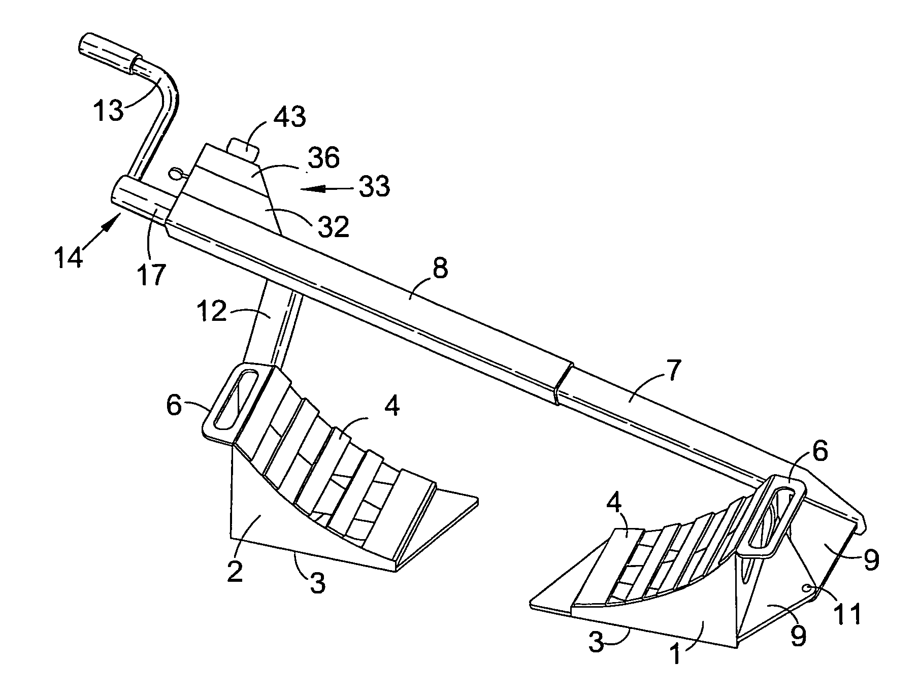
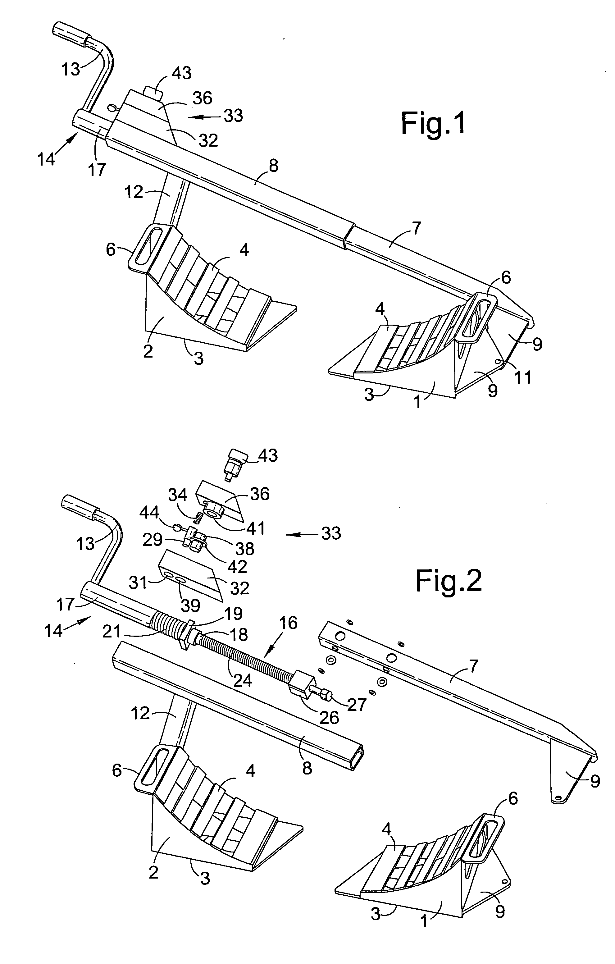
[0087] The immobilizing device, also referred to below as a safety device, illustrated in a first embodiment in FIGS. 1 to 4, comprises a first member 1 engageable with a first portion of a vehicle wheel (not shown), this portion being part of the tread of the tyre of the wheel near the location at which the tyre is in contact with the ground. A similar second member 2 is engageable with a second portion of the wheel; in this embodiment that portion is part of the tread of the tyre on the opposite side of the ground contact location.

[0088] The two members 1, 2 are each in the form of a chock, being wedge-shaped, and having a flat base 3 and an inclined upper surface 4 which, as shown, is preferably concave. Each chock 1, 2 has a lug 6 to facilitate handling. The chocks 1, 2 are mounted on respective elongate supports 7, 8 in the form of tubes which are preferably of polygonal section, more preferably rectangular section or square section, as shown. One support 7 is telescopically sl...

second embodiment

[0101] FIGS. 5 to 9 show the immobilizing device, in which a pneumatic drive is used to move the first and second members. The device resembles a wheel clamp and comprises a base frame 51, having an elongate front part 52 and a pair of side parts 53, 54, mounted on four castors 56. A front panel 57 rises from the front part 52 and prevents tampering.

[0102] The immobilizing device has a fixed chock 58 and a movable chock 59. The chocks 58, 59 are connected by respective pivots 61, 62 to respective supports 63, 64. The support 63 is fixed to on side part 53 of the base frame 51. The support 64 is connected to a driving device or mechanism constituted by a pneumatic piston-and-cylinder device 66. Compressed air fed to the cylinder 67 forces the piston 68 into the cylinder and causes the chock 59 to be drawn towards the chock 58. The compressed air is generated manually by a reciprocating pump 69 comprising a cylinder 71 containing a piston 72 driven back and forth by a handle 73 pivota...

third embodiment

[0123] FIGS. 22 to 26 show the immobilizing device, in which a rack and pawl drive is used to move the first and second members towards each other and in which engagement with a vehicle wheel is detected by the movement of one member against spring resistance. The device comprises a first member or chock 101 fixed on a first elongate support 102 telescopically slidable in a second elongate support 103 on which a second member or chock 104 is mounted by means of a pivot 106 with a vertical axis 107.

[0124] A foot-operated lever or pedal 108 is mounted by means of a horizontal pivot pin 109 on a bracket 111 fixed on the second support 103. A pawl 112, connected to the lever 108 by a pivot pin 113, acts on a ratchet 114, formed on the first support 102, so as to urge the first support into the second support 103 when the lever 108 is depressed, thereby moving the two chocks 101, 104 towards each other. The lever 108 is returned to its normal position (FIGS. 22 and 25) by a coil spring 1...


PUM


Abstract

An immobilizing device has a driving mechanism which urges two members or chocks towards each other to clamp a vehicle wheel between them. A detector, including a spring, detects engagement between the chocks and the wheel, in particular when the force applied by the driving mechanism exceeds a threshold, and permits operation of an auxiliary device, e.g. comprising a spring-loaded pin, to prevent movement of the chocks away from each other.

Description

BACKGROUND OF THE INVENTION [0001] 1. Technical Field [0002] This invention relates to a device for immobilizing a vehicle and to apparatus for preventing a vehicle from being driven away from a loading bay during loading / unloading. [0003] 2. Description of Related Art [0004] The normal sequence of events is that a vehicle (a semi-trailer, a drawbar trailer, or a lorry) is driven up to a loading bay and the driver contacts staff in the building. The loading bay has a door, usually of the ‘up and over’ type, and a dock leveller. The dock leveller is a powered ramp which is adjusted in height to accommodate differences in vehicle loading heights and to enable forklifts to drive from the building into the vehicle. To prevent accidents several safeguards are currently employed. Current systems include: [0005] Traffic lights, some of which are linked to the dock leveller. This does not prevent the driver from moving off but relies upon him obeying the lights. These systems are quite expe...

Claims


Application Information

Patent Timeline
Patent Type & Authority Applications(United States)
IPC IPC(8): G01C15/00B60R25/09B60R99/00B60T3/00B65G69/00B65G69/28
CPCB60R25/09B65G69/2882B65G69/005B60T3/00
Inventor MILNER, DAVID ANTHONYDRUMMOND, MICHAELFOULGER, DAVID LESLIECOWEN, NICHOLASHARKER, BENJAMIN
Owner CASTELL SAFETY INT
Why Eureka
Try Eureka