
Controlling method and system for led-based backlighting source

a technology of led backlighting and control method, which is applied in the direction of electric variable regulation, process and machine control, instruments, etc., can solve the problems of increasing the cost and complexity of the monitoring system, and the insufficient monitoring uniformity of single sensor and the use of multiple sensors

Active Publication Date: 2007-03-08
AU OPTRONICS CORP
View PDF5 Cites 42 Cited by
  • Summary
  • Abstract
  • Description
  • Claims
  • Application Information

AI Technical Summary

Benefits of technology

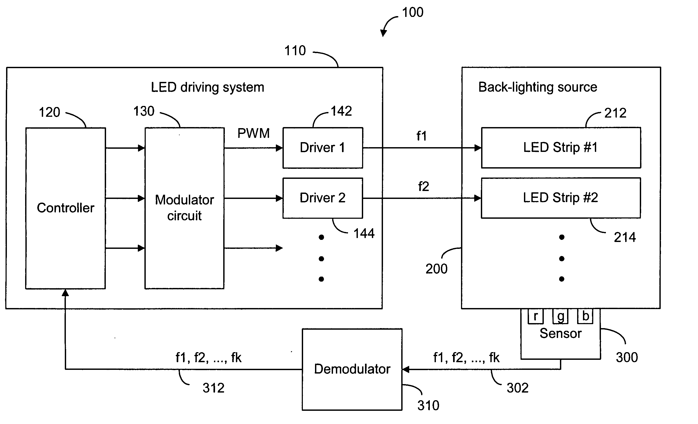
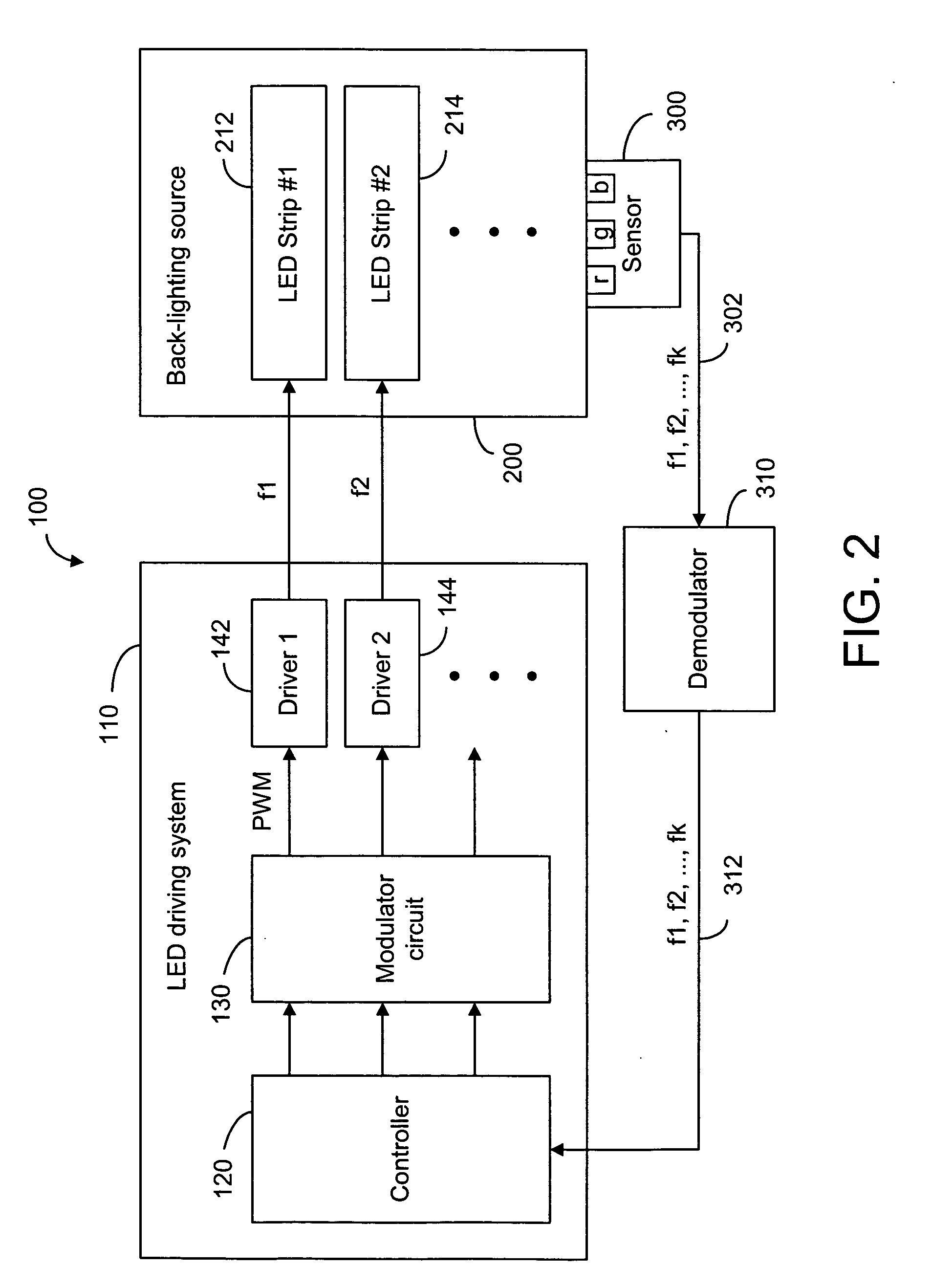
"The present invention is about improving the uniformity and color levels of a back-lighting source used in electronic devices. It does this by using different frequencies to drive the LED strips in the source. The strips can be assigned to different frequencies or divided into groups and each group can have a different frequency. The invention also includes color sensors to measure the brightness and color levels of the source. The assignment of driving frequencies can be based on the location of the strips to account for distance from the LED strips to the sensors. Overall, the invention allows for better control and adjustment of the back-lighting source."

Problems solved by technology

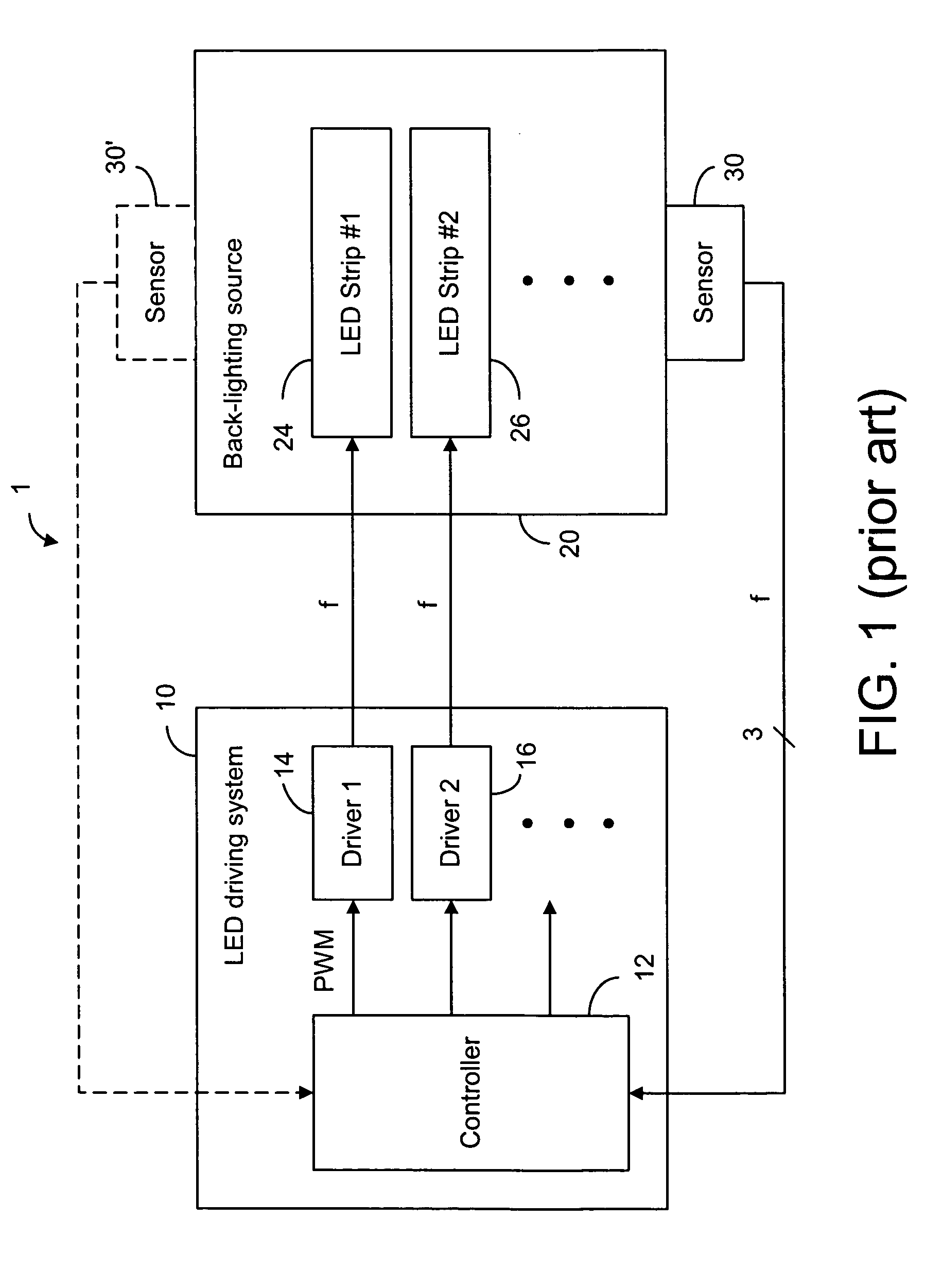
However, a single sensor may not be sufficient in monitoring the uniformity of the light output throughout the back-lighting source.
The use of multiple sensors increases the cost and the complexity of the monitoring system.

Method used


Image

  • Controlling method and system for led-based backlighting source
  • Controlling method and system for led-based backlighting source
  • Controlling method and system for led-based backlighting source

Examples


Embodiment Construction

[0013] As with the prior art method, the present invention also uses pulse-width modulation to change the duty cycle in each of the LED strips in order to control the brightness of the LED strips. In contrast to the prior art method, the present invention assigns different frequencies to the LED strips so as to monitor the spatial uniformity of the back-lighting source. As shown in FIG. 2, the back-lighting control system 100, according to the present invention, comprises an LED driving system 100 for driving a back-lighting source 200. The back-lighting source 200 comprises a plurality of LED strips 212, 214, . . . driven by a plurality of LED drivers 142, 144, . . . in the LED driving system 110. A sensor module 300 comprising a plurality of sensors (not shown) sensitive to different color components is used to sense the color levels in the back-lighting source 200. In the LED driving system 110, a controller 120 is used to adjust the brightness of the LED strips 212, 214, . . . b...


PUM


Abstract

The present invention uses different frequencies to drive the LED strips in the back-lighting source so that the spatial uniformity of the back-lighting source as well as the color levels in the source can be monitored and adjusted. Each individual strip is assigned to a different frequency. Alternatively, the strips are divided into groups and each group is assigned to a different frequency. A group may comprise two or more strips. Furthermore, some groups may have more strips than the other groups and the number of LEDs in one strip may be different from the number in other strips. The brightness uniformity and the color levels in the back-lighting source are sensed by one or more groups of color sensors in R, G and B. The assignment of driving frequencies can be based on the location of the strips.

Description

FIELD OF THE INVENTION [0001] The present invention relates generally to a light source for back-lighting an LCD panel and, more generally, to a method and system for controlling the light source. BACKGROUND OF THE INVENTION [0002] A display panel such as a transmissive or transflective liquid crystal display (LCD) panel requires a back-lighting source for illumination. Light-emitting devices (LEDs) are commonly used in such a back-lighting source. In particular, LEDs in red, green and blue colors are used to provide a back-light source in “white” color. To illuminate a large LCD panel, many strips of LEDs in different colors are used in a back-light source. The LED strips in different colors are driven by different LED drivers. [0003] In order to control the “whiteness” of the back-lighting source, three sets of sensors are typically used to sense the color brightness level in red, green and blue separately. The sensed color levels are conveyed to a processing means in a feedback c...

Claims


Application Information

Patent Timeline
Patent Type & Authority Applications(United States)
IPC IPC(8): H05B39/00
CPCH05B33/0869H05B33/0818G09G3/3413G09G3/342G09G2320/0242G09G2320/041G09G2320/064G09G2320/0666G09G2360/145H05B45/22
Inventor LIN, HSIN-WULIU, JEN-CHIHUANG, JYH-HAUR
Owner AU OPTRONICS CORP
Learn More