Visible light communication system and method therefor

Inactive Publication Date: 2007-03-15
KK TOSHIBA
View PDF13 Cites 172 Cited by
  • Summary
  • Abstract
  • Description
  • Claims
  • Application Information

AI Technical Summary

Benefits of technology

[0014] According to an aspect of the present invention, there is provided a visible light communication system including a transmission device which transmits a visible light signal and a reception device which receives the visible light signal, the transmission device comprising: light emission means for emitting visible lights of red, green and blue; data modulation means for assigning 1-bit in

Problems solved by technology

However, in a case where high-speed communication is to be realized by increasing the modulation speed, it is

Method used


Image

  • Visible light communication system and method therefor
  • Visible light communication system and method therefor
  • Visible light communication system and method therefor

Examples


first embodiment

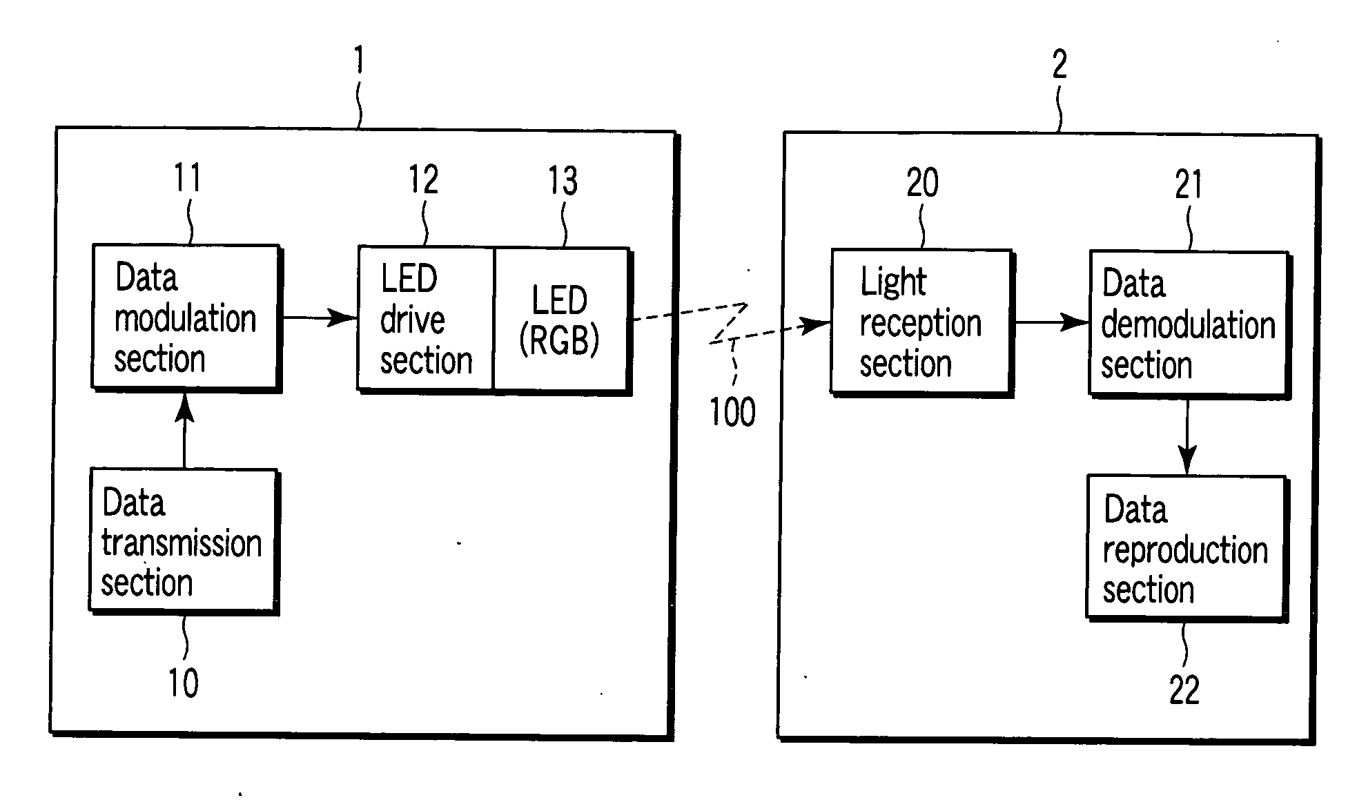
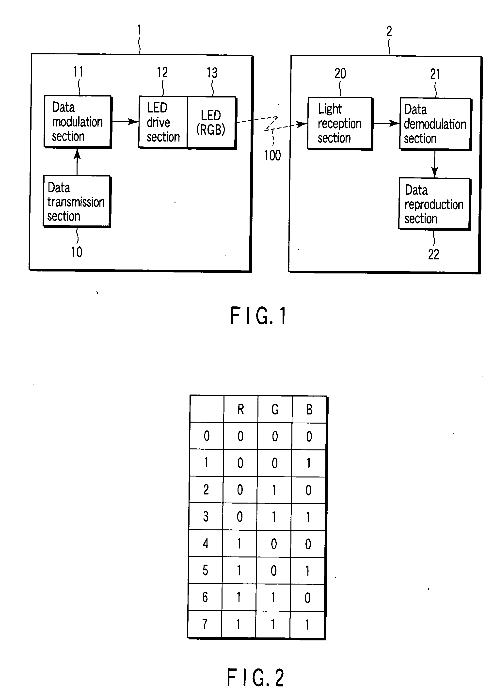
[0026]FIG. 1 is a block diagram showing the structure of a visible light communication system according to a first embodiment of the present invention.

[0027] The system of this embodiment includes a transmission device 1, which is built, for example, in a personal computer, and a reception device 2 which is built, for example, in an AV apparatus. This system executes data communication by a multiplexed visible light signal 100. Needless to say, the transmission device 1 and reception device 2 are not limited to the built-in type devices, and may be external-attachment type devices.

[0028] The transmission device 1 includes a data transmission section 10, a data modulation section 11, and an LED light emission section 13 having LED elements of RGB. The data transmission section 10 outputs, for example, digital audio data as transmission data. As will be described later, the data modulation section 11 assigns 1 bit to each of visible lights of RGB, modulates the transmission data and...

second embodiment

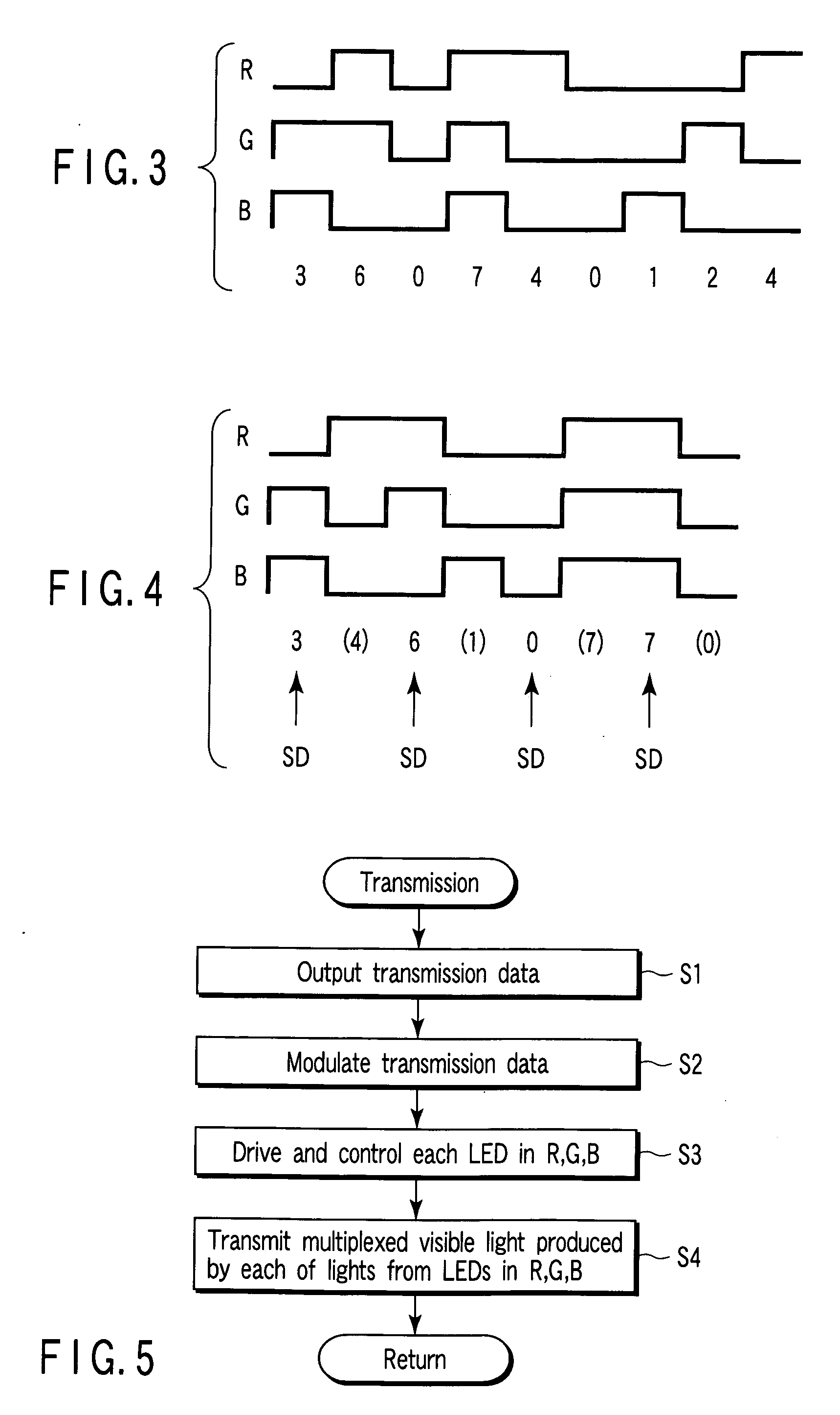
[0038]FIG. 4 and FIG. 7 relate to a second embodiment of the invention. The structure of the visible light communication system is the same as shown in FIG. 1. An overlapping description with the first embodiment is omitted.

[0039] As described in connection with the first embodiment, the transmission device 1 transmits data as a multiplexed visible light signal in which RGB visible lights are modulated. In this case, in normal cases, the multiplexed visible light of RGB is emitted as white light. However, in actual data transmission, the frequency of occurrence of RGB is non-uniform, and the RGB multiplexed visible light is possibly emitted not as white visible light but as visible light that varies in seven colors.

[0040] The present embodiment relates to a transmission device 1 wherein a white variation of the RGB multiplexed visible light is suppressed, and the RGB multiplexed visible light, which is transmitted, is always maintained as white visible light. The embodiment is des...

third embodiment

[0047]FIG. 8 to FIG. 10 relate to a third embodiment of the invention.

[0048] As is shown in FIG. 8, the system of this embodiment includes a transmission device 8, which is built, for example, in a personal computer, and a reception device 9 which is built, for example, in an AV apparatus. This system executes data communication by a multiplexed visible light signal 200. Needless to say, the transmission device 8 and reception device 9 are not limited to the built-in type devices, and may be external-attachment type devices.

[0049] The transmission device 8 includes a data transmission section 80, a data modulation section 81, and an LED light emission section 83 having LED elements of RGB. The data transmission section 80 outputs, for example, three kinds of audio data of different contents as transmission data. For example, the data transmission section 80 outputs audio data of three languages (Japanese, English and Spanish) as transmission data. The data modulation section 81 mo...


PUM


Abstract

In a visible light communication system, a transmission device includes a data modulation section which assigns 1-bit information to each of visible lights of RGB, and modulates transmission data into 3-bit modulation data. An LED light emission section transmits a multiplexed visible light signal, in which the RGB visible lights are multiplexed in accordance with the modulation data.

Description

CROSS-REFERENCE TO RELATED APPLICATIONS [0001] This application is based upon and claims the benefit of priority from prior Japanese Patent Application No. 2005-265694, filed Sep. 13, 2005, the entire contents of which are incorporated herein by reference. BACKGROUND OF THE INVENTION [0002] 1. Field of the Invention [0003] The present invention relates generally to a visible light communication system which makes use of visible light, and more particularly to a visible light communication system which makes use of a multiplexed visible light signal in which RGB visible lights are multiplexed. [0004] 2. Description of the Related Art [0005] In recent years, a visible light communication system which makes use of visible light has steadily been developed. There have been proposed visible light communication systems which use, as light sources, light-emitting diodes (LEDs) or light sources for illumination (see, e.g. Patent Document 1). [0006] Also proposed is a visible light communica...

Claims


Application Information

Patent Timeline
IPC IPC(8): H04B10/04H04B10/11H04B10/116H04B10/524H04B10/54
CPCH04B10/116H04B10/1141
Inventor SUZUKI, KATSUYOSHI
Owner KK TOSHIBA
Why Eureka
Try Eureka