Compact suture punch with malleable needle

Active Publication Date: 2007-03-15
ARTHREX
View PDF91 Cites 17 Cited by
  • Summary
  • Abstract
  • Description
  • Claims
  • Application Information

AI Technical Summary

Benefits of technology

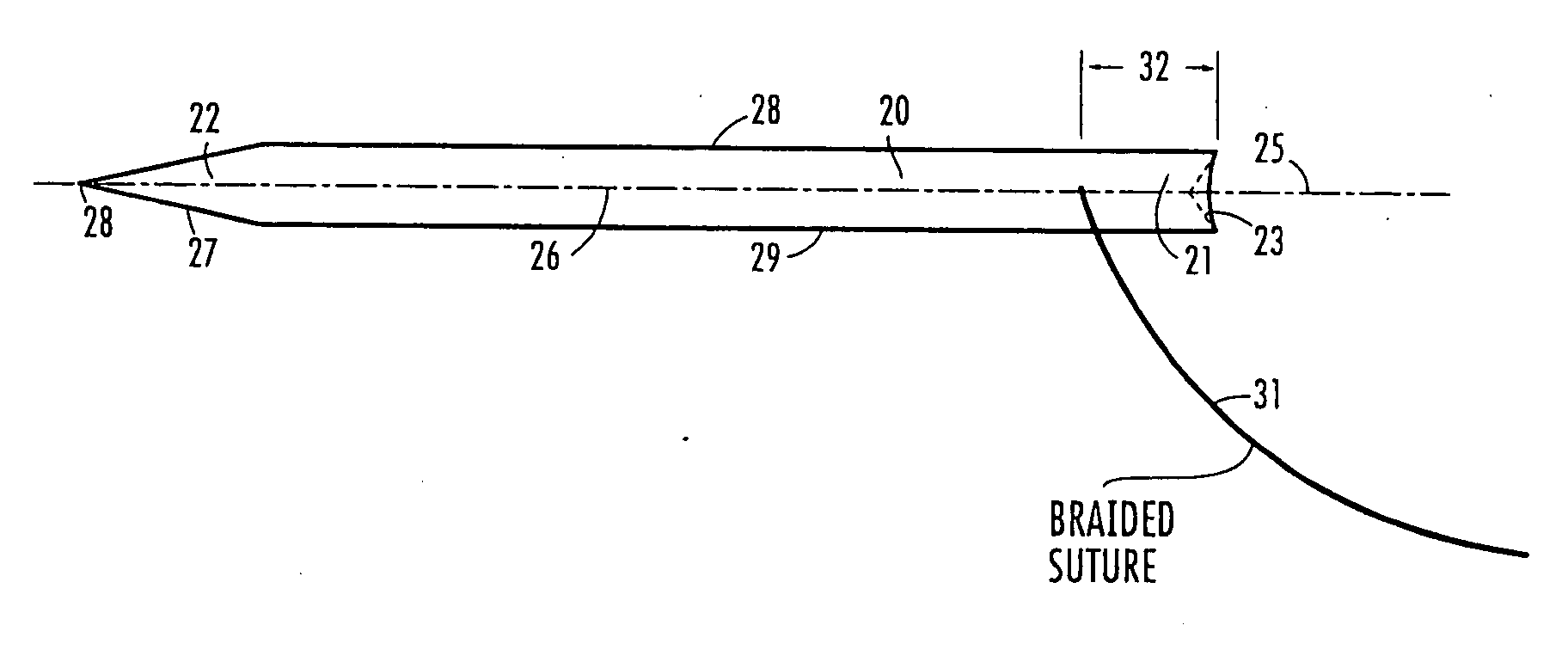
The present invention relates to an improved method and apparatus for suturing tissue with a specialized tool called a suturing instrument. This instrument has two main parts: a malleable needle made from titanium or other suitable metal, which can be bent into different shapes to securely hold and delivery suture materials to the tissue being treated; and a small handheld device designed to push the needle through the skin and into the tissue. When this happens, the needle becomes flexible and delivers the suture material deeper into the tissue without getting stuck. A unique feature of this design is its ability to bend around tight angles and straight lines, making it easier to reach areas difficult to access while still maintaining control over the direction of the needle's movement. Overall, this new system allows surgeons to more easily and accurately close wounds and minimize damage during surgery.

Problems solved by technology

The technical problem addressed in this patent text is the need for a suture punch that can pass braided suture without the use of a shuttle or similar means. Existing devices have limitations in terms of requiring multiple or complex sequential operations or a high level of surgeon skill. The invention proposes a solution by using a Nitinol alloy that has the ability to deform and return to its original shape when in an unconstrained condition. The suture punch is designed to pass through a small diameter cannula and create a small hole in the tissue for suturing.

Method used


Image

  • Compact suture punch with malleable needle
  • Compact suture punch with malleable needle
  • Compact suture punch with malleable needle

Examples


Embodiment Construction

[0146] The present invention is more particularly described in the following examples that are intended to be illustrative only since numerous modifications and variations therein will be apparent to those skilled in the art. As used in the specification and in the claims, the singular form “a,”“an,” and “the” may include plural referents unless the context clearly dictates otherwise. Also, as used in the specification and in the claims, the term “comprising” may include the embodiments “consisting of” and “consisting essentially of.”

[0147] The present invention will now be further described through the following drawings. It is to be understood that these drawings are non-limiting and are presented to provide a better understanding of various embodiments of the present invention and are not intended to represent every possible embodiment of the present invention.

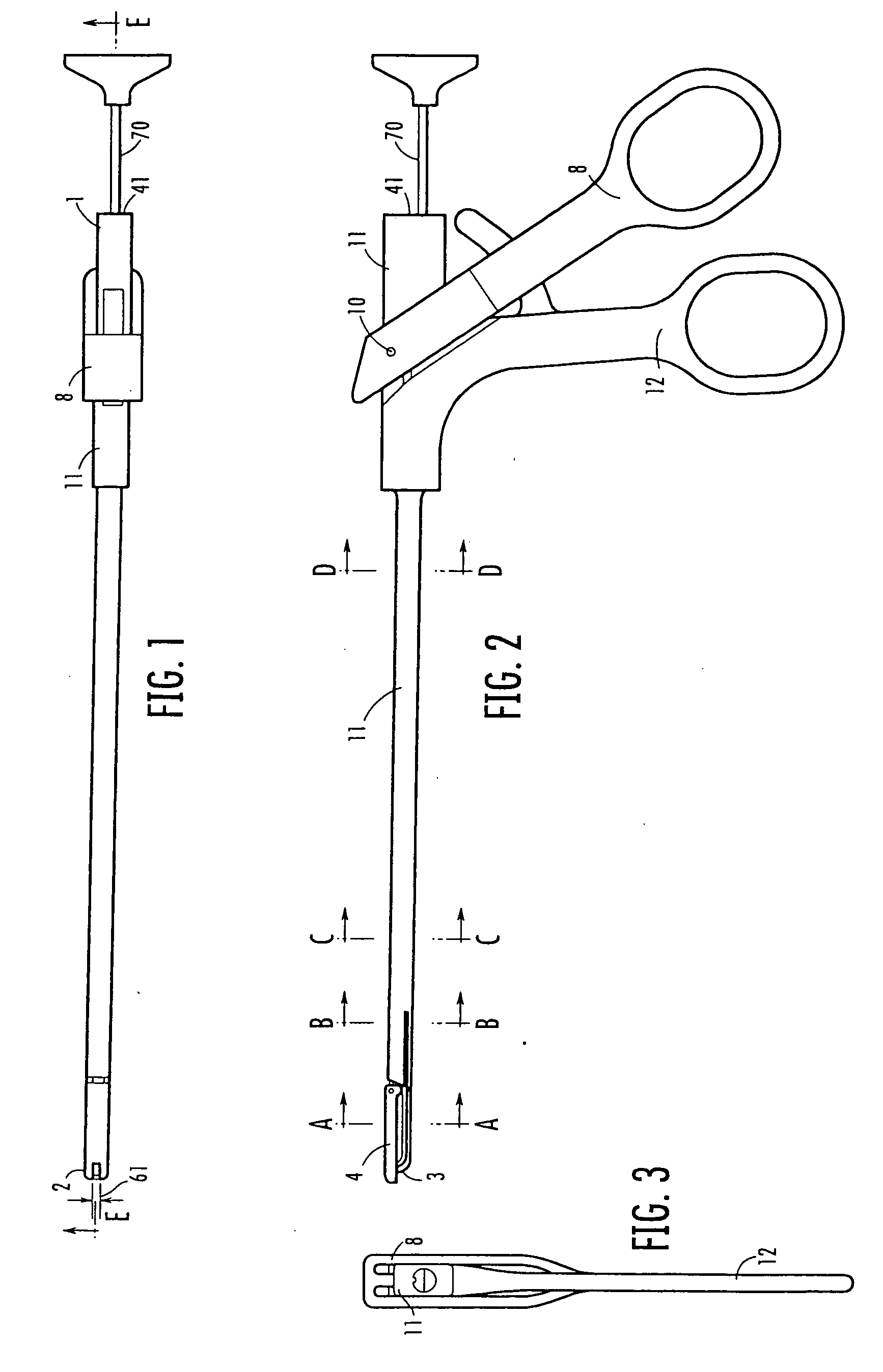
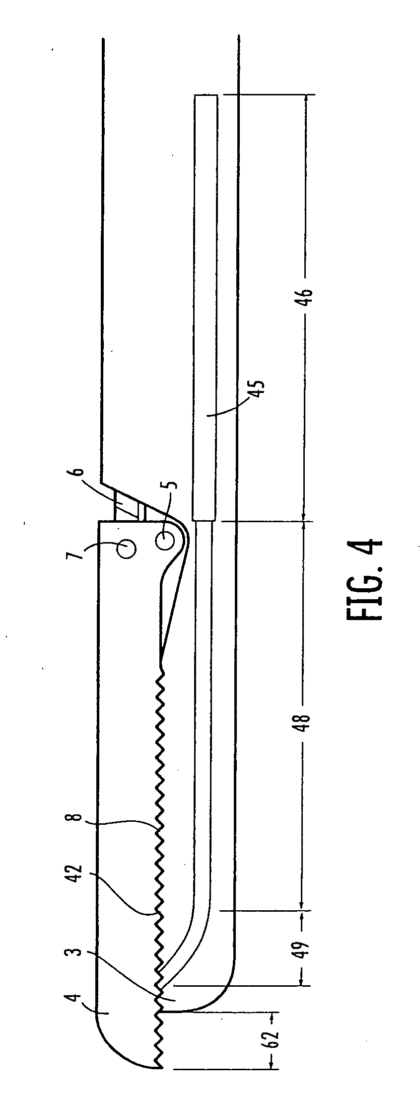
[0148] Referring to the drawings, as best seen in FIGS. 1 through 9, the instrument body 11 has a proximal end 1 and a d...


PUM


Abstract

A suture punch system that is capable of directly passing braided suture through tissue in a simple, one-step process. The system includes three principle components: a malleable needle capable of delivering the suture to the tissue, a handheld instrument for grasping tissue and controlling needle placement, and a force-supplying mechanism to supply the force required for needle placement. Needle deformation begins at the tip of the instrument, which beneficially includes a curved segment. As the distal tip of the needle pierces the tissue, it continues its radial path through the tissue. When the proximal end of the needle exits from the instrument, the needle may be radial in shape and traverses an essentially radial path through the tissue. Once the needle has passed entirely through the tissue, it may be retrieved using the jaws of the punch or another instrument.

Description


Claims


Application Information

Patent Timeline
Owner ARTHREX
Why Eureka
Try Eureka