Steering apparatus
a technology of steering wheel and steering column, which is applied in the direction of steering column, steering control, steering control of vehicle, etc., can solve the problems of complex operation, difficult reduction of the cost of the steering wheel adjusting apparatus, and difficulty in reducing the position of the steering wheel
- Summary
- Abstract
- Description
- Claims
- Application Information
AI Technical Summary
Benefits of technology
Problems solved by technology
Method used
Image
Examples
second embodiment
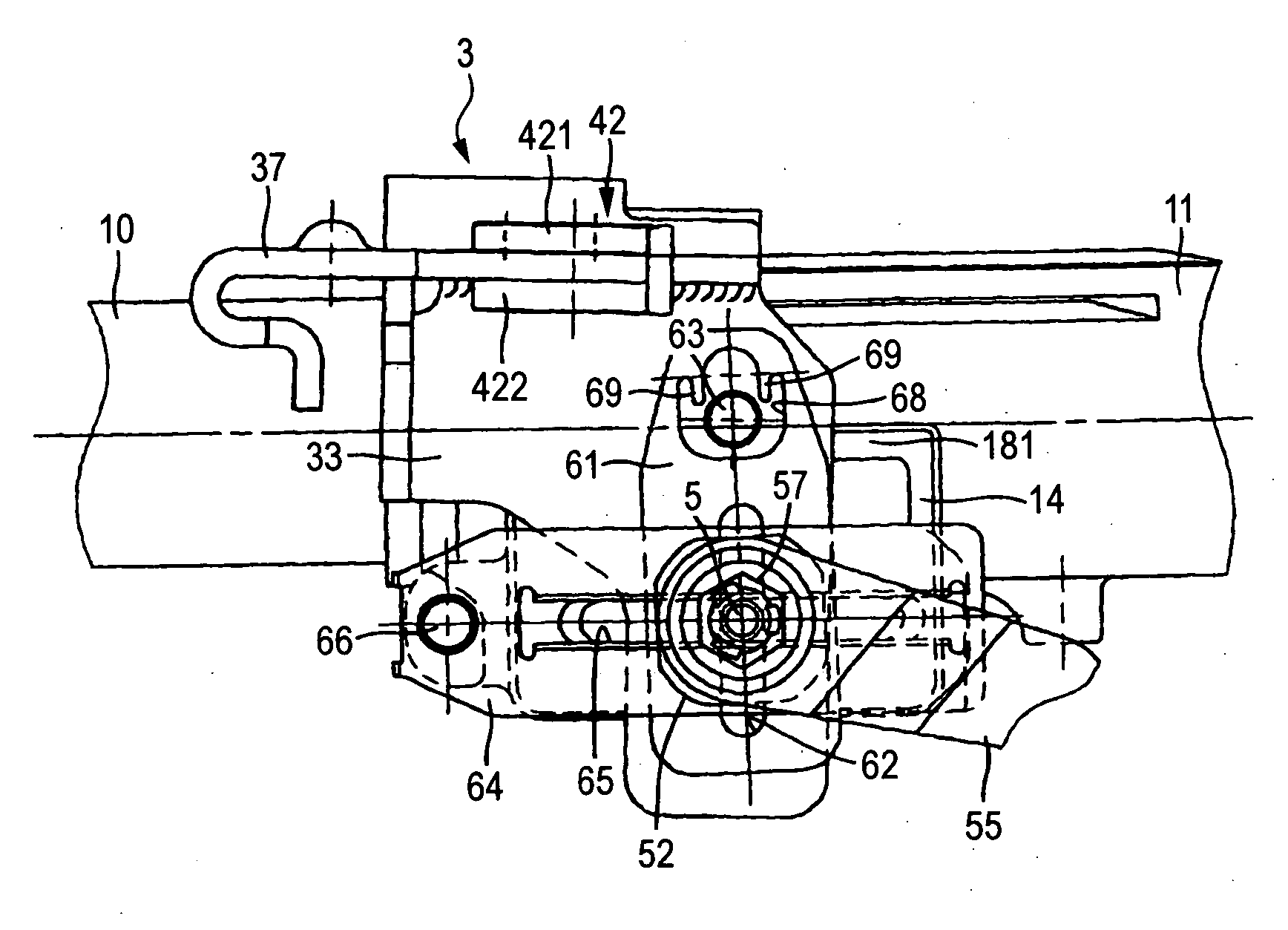
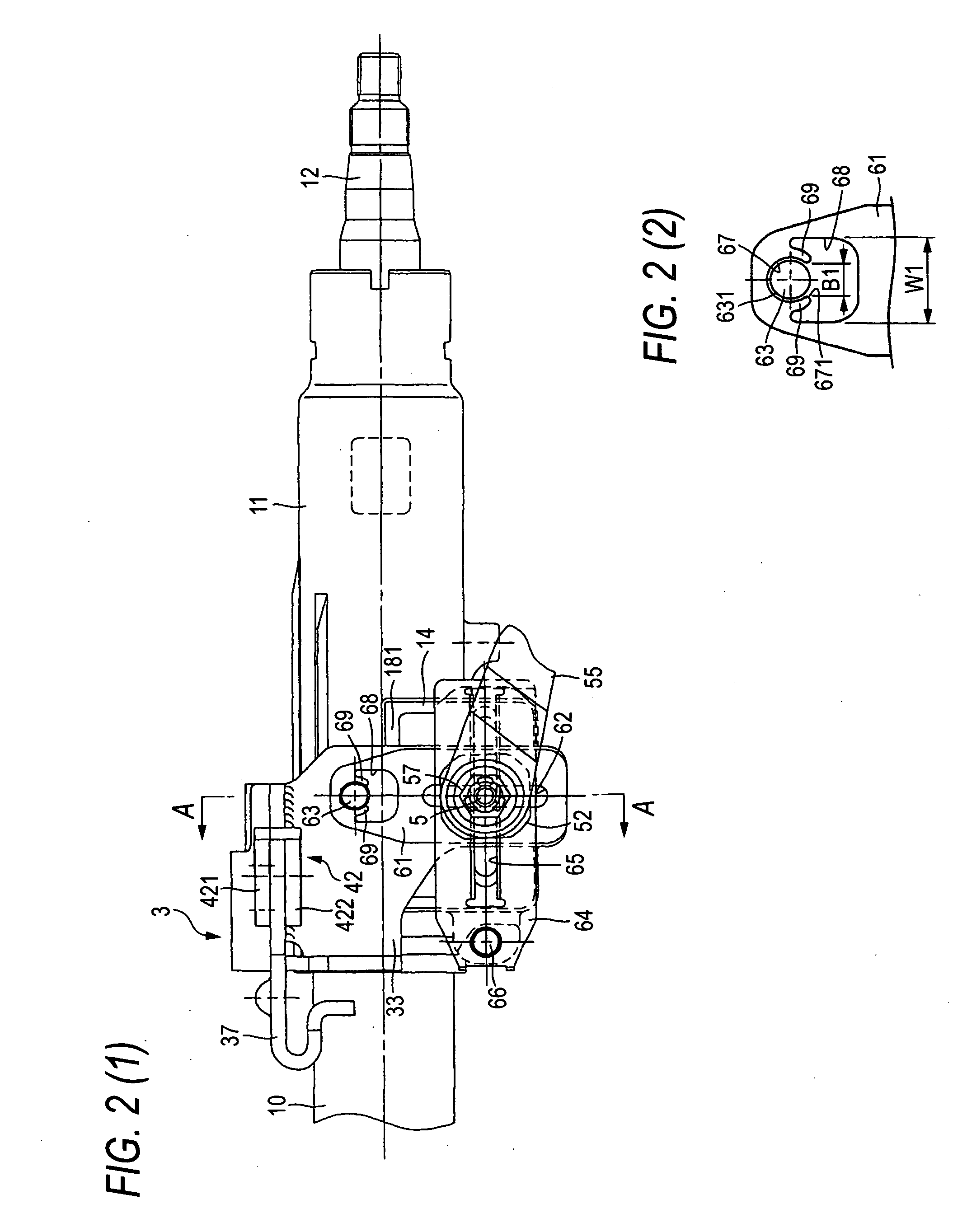
[0155] Next, a second embodiment of the invention is described below. FIG. 6 is a front view illustrating a primary part of the second embodiment of the steering apparatus according to the invention. In the following description, only constituent elements differing from those of the first embodiment are described. Redundant descriptions are omitted. Additionally, the same reference numeral designates the same component as that of the first embodiment.
[0156] The second embodiment is a modification of the first embodiment and enables the cancellation of both the connection between the tilt friction plate 61 and the vehicle-body-mounted bracket 3 and the connection between the telescope friction plate 64 and the outer column 11.
[0157] That is, as shown in FIG. 6, the structure of the connection portion between the tilt friction plate 61 and the bolt 63 is the same as that of the first embodiment. Therefore, the description of the structure of the connection portion therebetween is om...
third embodiment
[0165] Next, a third embodiment of the invention is described below. FIG. 7 is a front view illustrating a primary part of the third embodiment of the steering apparatus according to the invention. In the following description, only constituent elements differing from those of the above embodiments are described. Redundant descriptions are omitted. Additionally, the same reference numeral designates the same component as that of the first embodiment.
[0166] Similarly to the second embodiment, the third embodiment enables the cancellation of both the connection between the tilt friction plate 61 and the vehicle-body-mounted bracket 3 and the connection between the telescope friction plate 64 and the outer column 11. The third embodiment differs from the second embodiment in that the structure of the connection portion between the telescope friction plate 64 and the outer column 11.
[0167] That is, as shown in FIG. 7, the structure of the connection portion between the tilt friction p...
embodiment a
[0234] FIGS. 9 to 13 illustrate a embodiment (A) of the invention, which corresponds to the aspect (A) of the invention. The embodiment (A) features that the first friction member 1035 and the second friction member 1036, each of which is of the integral body, are used to facilitate the fabrication of the apparatus of adjusting the position of the steering wheel. The structure and the operation of the rest of the apparatus are similar to those of the related apparatus shown in FIGS. 18 and 19. Thus, the drawing and the description of such equivalent portions are omitted or simplified. The following description focuses on the features of the invention. The present embodiment is an example of applying the invention to a structure enabled to adjust the up / down position and the anteroposterior position of the steering wheel 1001 (see FIG. 18).
[0235] Thus, first elongated holes 1026, 1026, which are elongated in a direction substantially perpendicular to the direction of an axis of a st...
PUM
 Abstract
Description
Claims
Application Information
 - R&D
- Intellectual Property
- Life Sciences
- Materials
- Tech Scout
- Unparalleled Data Quality
- Higher Quality Content
- 60% Fewer Hallucinations
Browse by: Latest US Patents, China's latest patents, Technical Efficacy Thesaurus, Application Domain, Technology Topic, Popular Technical Reports.
© 2025 PatSnap. All rights reserved.Legal|Privacy policy|Modern Slavery Act Transparency Statement|Sitemap|About US| Contact US: help@patsnap.com


