Ultrasonic welding system

a welding system and ultrasonic technology, applied in the direction of soldering equipment, manufacturing tools, auxillary welding devices, etc., can solve the problems of surface oxidation, inconvenient welding, inability to complete welding, etc., and achieve high acceleration and speed, precise timing, and high versatility.

Inactive Publication Date: 2007-03-29
DELPHI TECH INC
View PDF8 Cites 45 Cited by
  • Summary
  • Abstract
  • Description
  • Claims
  • Application Information

AI Technical Summary

Benefits of technology

[0007] Advantages of the present invention include a highly versatile ultrasonic welding system capable of approaching a weld article within millimeters at high acceleration and speed without contacting the article. Once within a small dista

Problems solved by technology

This galling results in contaminants, such as for example surface oxidation, to be displaced.
Unfortunately, air cylinder speed does not change during the welding cycle.
This approximation also leads to inc

Method used


Image

  • Ultrasonic welding system
  • Ultrasonic welding system
  • Ultrasonic welding system

Examples


Embodiment Construction

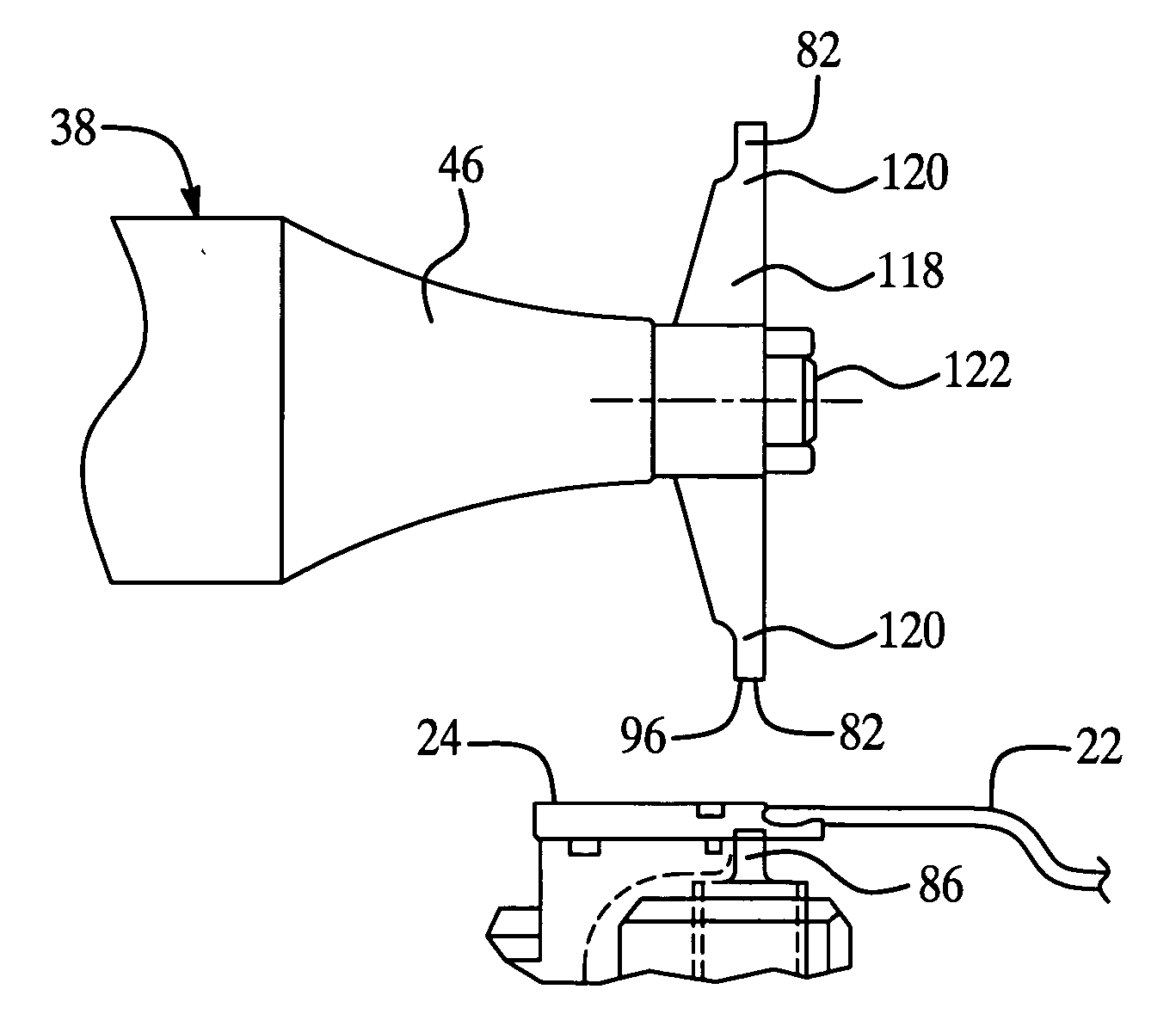
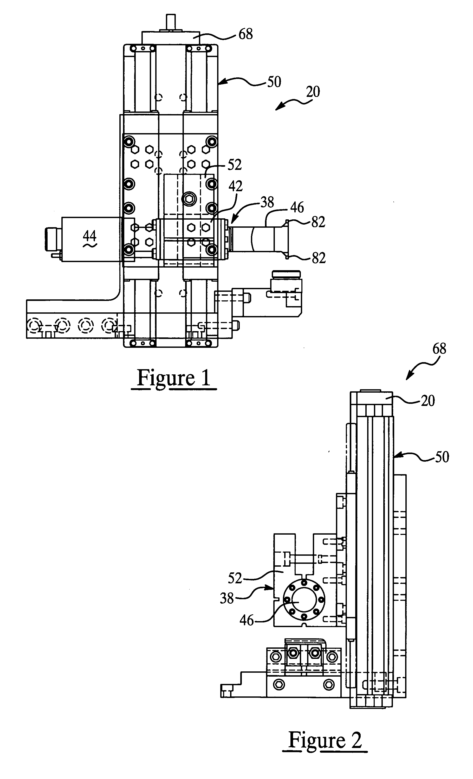
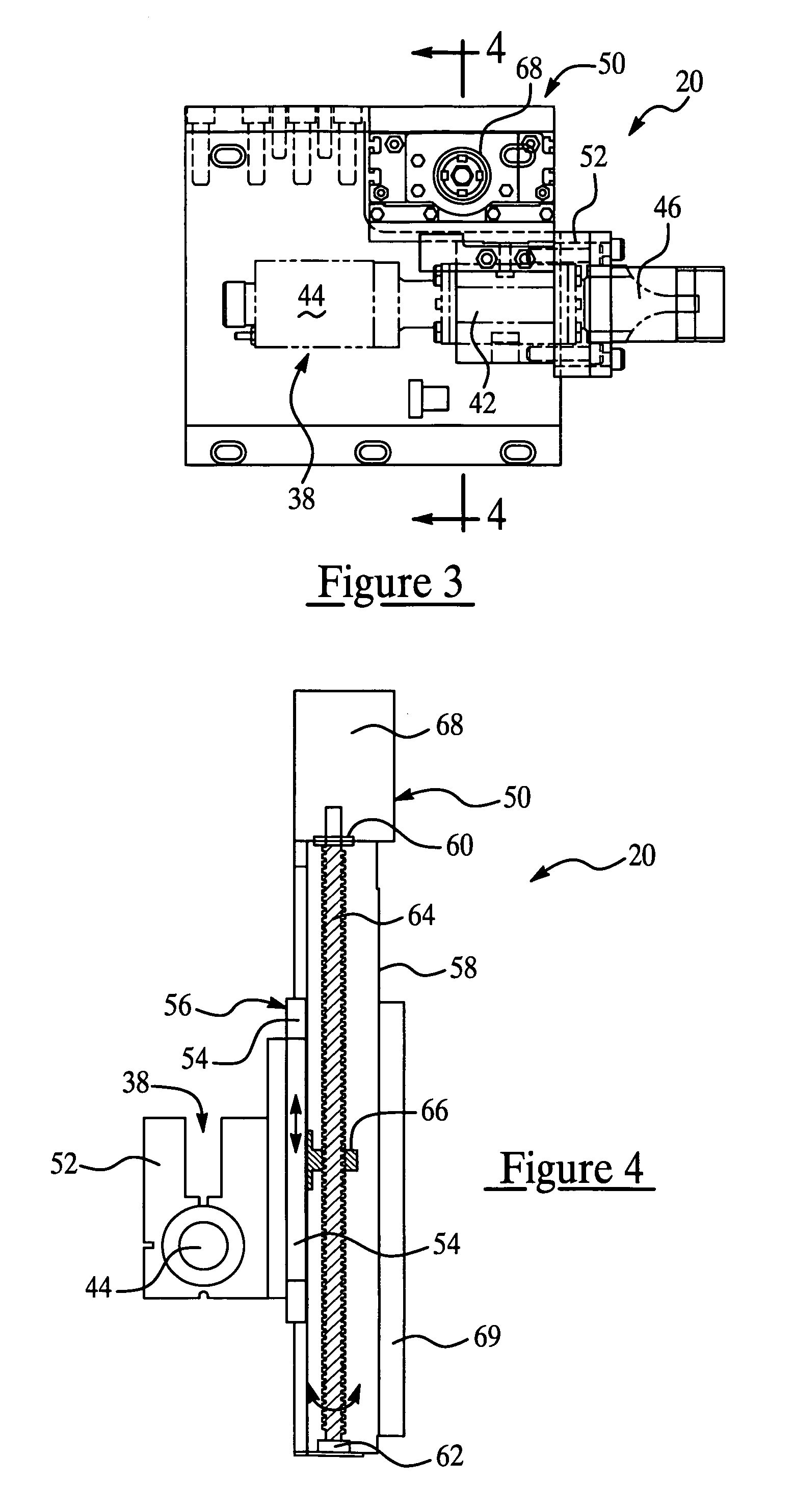
[0026] Referring to FIGS. 1-4 and 12-16 an ultrasonic welding system 20 of the present invention welds or galls a first workpiece 22 to a second workpiece 24 both being of generally like material. For the sake of example, and as illustrated as a preferred application but not limited to this application, the first and second workpieces 22, 24 are preferably made of substantially nonferrous metal. The first workpiece 22 as illustrated in FIG. 12 is preferably an electrically insulated wire having an outer electrically insulating jacket 26 and an inner electrically conductive core 28. The second workpiece 24 is preferably an electrical terminal that typically is first crimped to the insulation jacket 26 of the first workpiece 22 or insulated wire by a pair of terminal wings 30. In this example, contaminants which are generally polished away during the galling process are typically oxidation formed upon a contact surface 32 of the terminal 24, and the insulation jacket 26, itself, of th...


PUM

PropertyMeasurementUnit
Forceaaaaaaaaaa
Electrical conductivityaaaaaaaaaa
Lengthaaaaaaaaaa

Abstract

The present invention is an ultrasonic welding system having an ultrasonic welder integrated with a servo press for galling and ultrasonic welding of a first workpiece to a second workpiece. The first and second workpieces are substantially disposed between a confronting tip and stationary anvil of the ultrasonic welder. Prior to welding, the servo press preferably quickly moves the tip toward and generally against the first workpiece. During welding, a variable speed motor of the servo press preferably slowly moves the tip toward the anvil compressing the workpieces together while a transducer of the ultrasonic welder transmits mechanical vibration to the tip for welding the workpieces together.

Description

TECHNICAL FIELD [0001] The present invention relates to an ultrasonic welding system and more particularly to an ultrasonic welding system utilizing a servo press. BACKGROUND OF THE INVENTION [0002] Ultrasonic welding systems which attach like-material workpieces together are generally known, as exemplified in U.S. Pat. No. 6,588,646, issued Jul. 8, 2003 and incorporated herein in it's entirety. Ultrasonic welders utilize ultrasonic energy to join, for instance, plastic to plastic or nonferrous metal to nonferrous metal. Ultrasonic welding is not actually “welding” in the sense that there is no application of heat as is used in conventional welding, wherein metals are heated to the point of melting into each other. In the case of ultrasonic welding, the like-material workpieces are placed between a movable tip and a stationary anvil of the welder. A mechanical vibration is transmitted to the tip that is then applied to the workpieces. [0003] The frequency and the amplitude of the vi...

Claims


Application Information

Patent Timeline
IPC IPC(8): B23K37/00B23K5/20
CPCB23K20/106H01R4/023H01R43/0228H01R43/0207H01R4/026
Inventor HANDEL, JEFFREY M.CLARK, MATTHEW A.
Owner DELPHI TECH INC
Why Eureka
Try Eureka