Fastener driving device

a technology of driving device and fastener, which is applied in the direction of manufacturing tools, stapling tools, nailing tools, etc., can solve the problems of not being able to drive single shot pneumatic nailers, not being able to drive 1.5 inch long metal connector fasteners, and not being able to meet the requirements of metal connector applications

Active Publication Date: 2007-04-05
STANLEY FASTENING SYST LP
View PDF42 Cites 49 Cited by
  • Summary
  • Abstract
  • Description
  • Claims
  • Application Information

AI Technical Summary

Benefits of technology

[0006] Therefore, it is an aspect of the present invention to provide a fastener driving device that allows the tip of a fastener to be used to locate a hole in a metal connector and has the safety features of a conventional fastener driving device.

Problems solved by technology

Conventional fastener driving devices, such as pneumatic nailers, have been difficult to use in metal connector applications because of the size of such devices.
While framing nailers may be used to drive longer metal connector fasteners, they are typically not configured to drive shorter metal connector fasteners that are 1.5 inches in length.
There are currently no single shot pneumatic nailers available that are dedicated to only driving a metal connector fastener that has a length of about 1.5 inches.
Moreover, the design of conventional pneumatic nailers makes it difficult to accurately locate a fastener into the hole of the metal connector due to design of the nose and the contact arm.
Conversely, when driving a fastener through a hole of a metal connector, the precision of the drive is important because of the risk of damaging the nailer or the metal connector.
Although there have been attempts to use the tip of the fastener that is about to be driven as the hole locator, providing a robust and relatively inexpensive contact arm has been challenging.

Method used


Image

  • Fastener driving device
  • Fastener driving device
  • Fastener driving device

Examples


Embodiment Construction

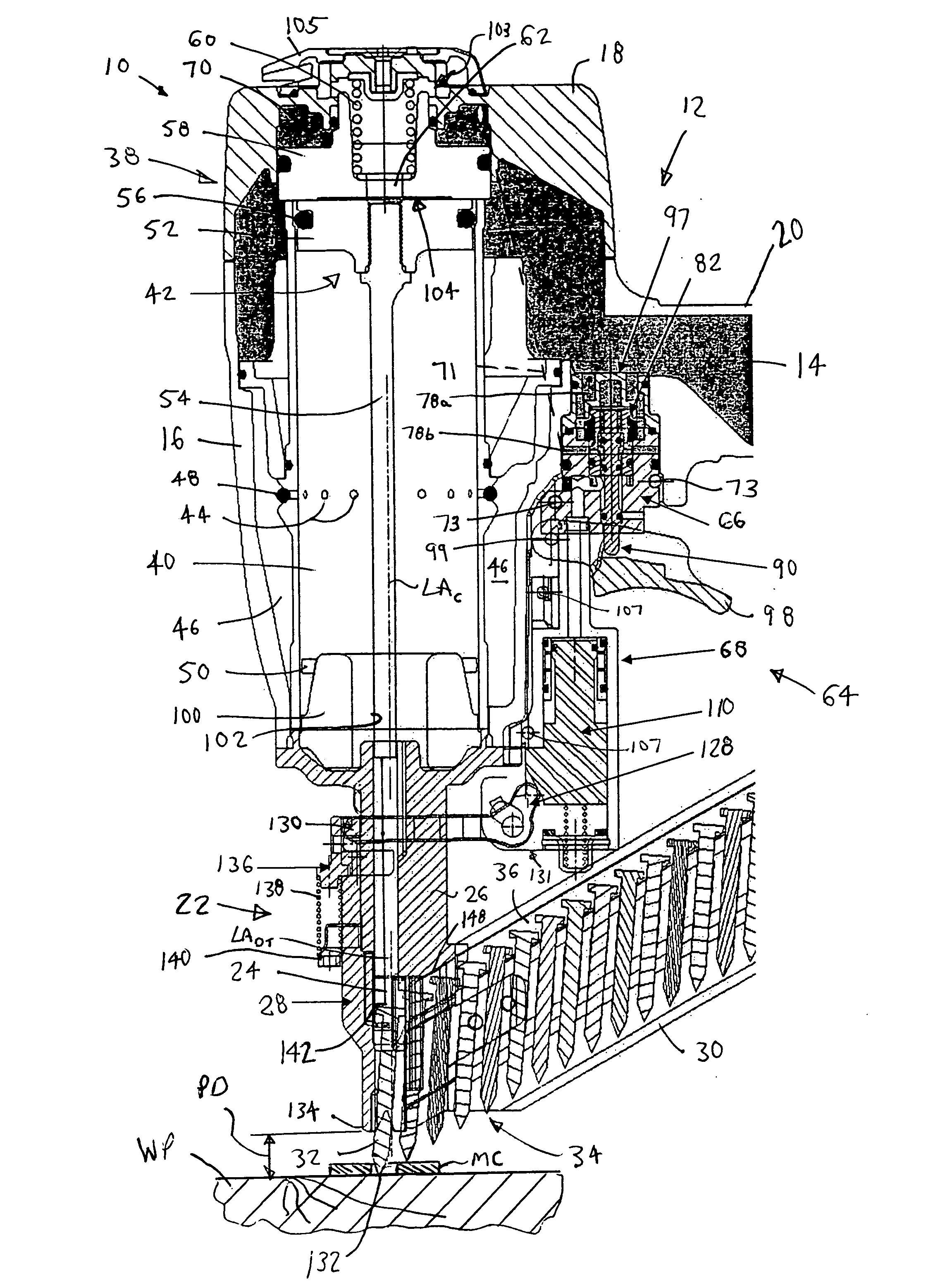
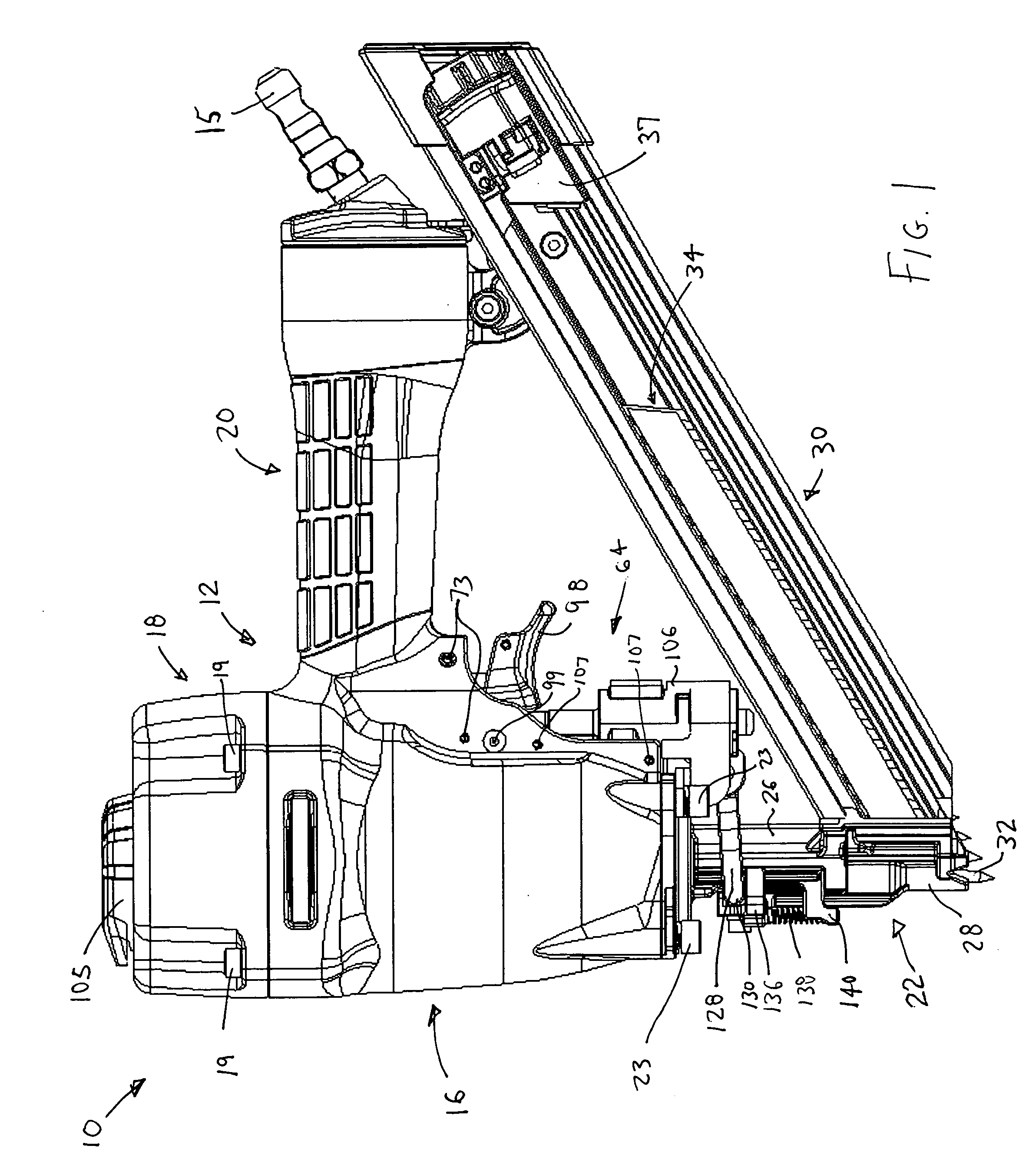
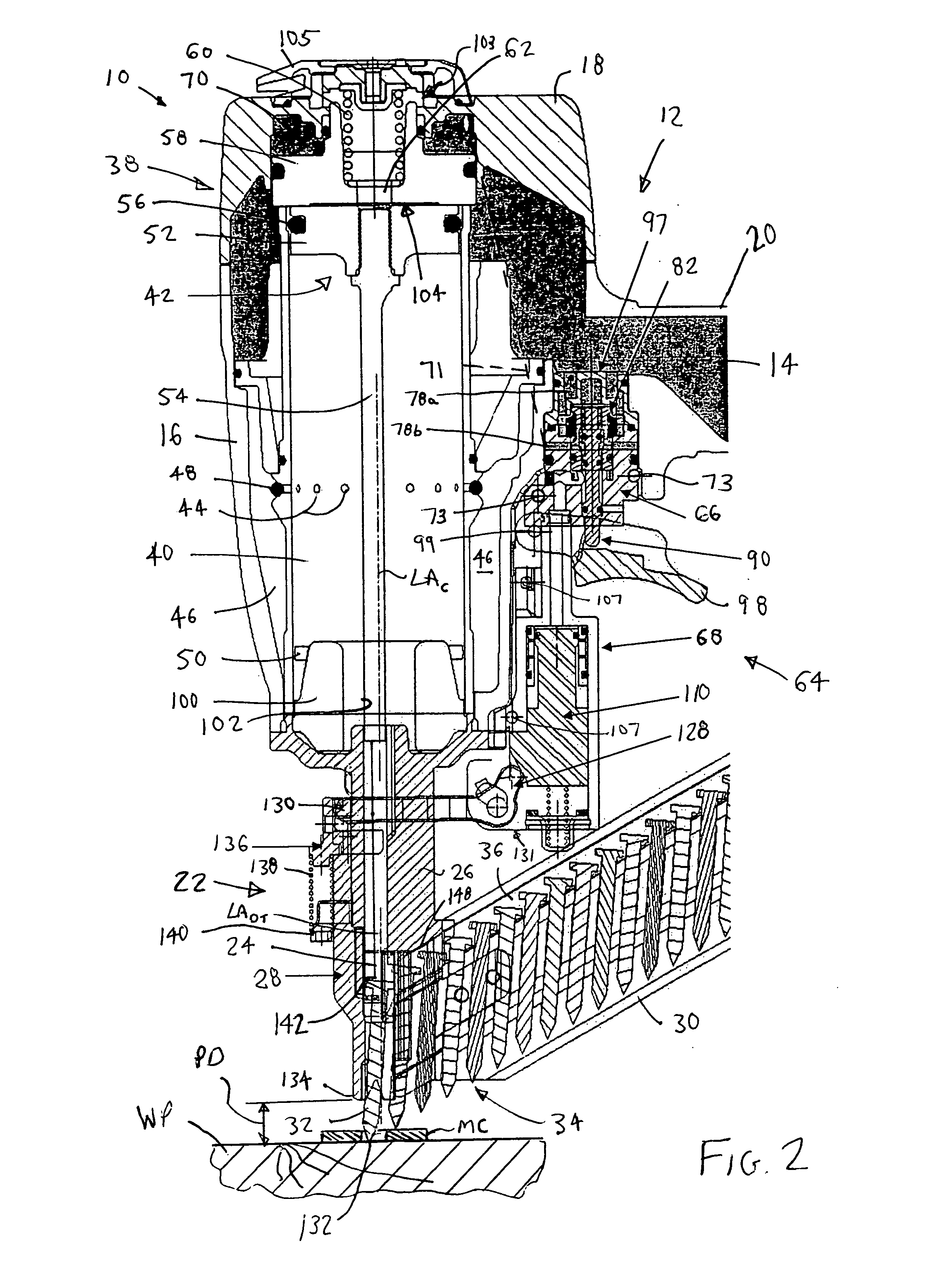
[0028]FIG. 1 illustrates a fastener driving device 10 according to an embodiment of the present invention. The device 10 includes a housing 12 that defines a reservoir 14 (see FIG. 2) therein. The housing 12 is preferably constructed from a lightweight yet durable material, such as magnesium. The reservoir 14 is configured to receive a pressurized gas that is used to power the device 10. In an embodiment, the pressurized gas may be provided to the reservoir 14 from a compressor through a hose. The hose may be connected to the device 10 via a fitting 15 that may be attached to the housing 12, or the pressurized gas may be provided to the reservoir 14 through a cartridge. For example, the pressurized gas may be air that has been compressed by a compressor, as is commonly used in pneumatic tools. It is also contemplated that any gas that releases energy upon expansion, such as a gas produced as a by-product of combustion, or a gas that is produced upon a phase transformation of a liqui...


PUM

PropertyMeasurementUnit
lengthaaaaaaaaaa
distanceaaaaaaaaaa
distanceaaaaaaaaaa

Abstract

A fastener driving device includes a nose assembly carried by a housing that has a reservoir. The nose assembly has a fastener drive track. At least a portion of the fastener drive track is defined by a movable portion of the nose assembly. A fastener driver is movably mounted in the housing and configured to enter the drive track and drive successive leading fasteners into a workpiece. A head valve is constructed and arranged to be actuated so as to allow the pressurized gas to move the fastener driver through an operating cycle. An actuator is constructed and arranged to actuate the head valve. The actuator includes a trigger valve constructed and arranged to allow passage of the pressurized gas from the reservoir to a chamber above the head valve, and a contact valve operatively connected to the movable portion of the nose assembly.

Description

BACKGROUND OF THE INVENTION [0001] 1. Field of the Invention [0002] The present invention generally relates to fastener driving devices, and more specifically relates to fastener driving devices that drive fasteners for connecting metal connectors to a workpiece. [0003] 2. Description of Related Art [0004] The construction industry has seen an increase in the use of metal connectors when joining two workpieces together. For example, joist hangers are commonly used in the construction of floors in buildings, as well as outdoor decks. Also, L-shaped metal connectors are used to connect and / or reinforce two workpieces that are joined perpendicularly, such as when connecting the framing of two walls. Conventional fastener driving devices, such as pneumatic nailers, have been difficult to use in metal connector applications because of the size of such devices. For example, a conventional pneumatic nailer used for framing applications is designed to drive nails that are 2-4 inches in leng...

Claims


Application Information

Patent Timeline
Patent Type & Authority Applications(United States)
IPC IPC(8): B25C1/04
CPCB25C1/008B25C1/043
Inventor TILLINGHAST, ADAMAGUIRRE, JUAN IGNACIOCANLAS, PRUDENCIO S. JR.
Owner STANLEY FASTENING SYST LP
Why Eureka
Try Eureka