Control circuit for overcoming stiction

a control circuit and stiction technology, applied in the manufacture of microstructural devices, instruments, optics, etc., can solve the problems of affecting the operation of the device, affecting the function of the device, and not eliminating the stiction

Inactive Publication Date: 2007-04-05
HEWLETT PACKARD DEV CO LP
View PDF10 Cites 93 Cited by
  • Summary
  • Abstract
  • Description
  • Claims
  • Application Information

AI Technical Summary

Problems solved by technology

MEMS functionality is often degraded or even destroyed by a phenomenon called stiction.
While these steps may reduce the effects of stiction to a degree, none have eliminated stiction as a factor in the operation of MEMS.

Method used


Image

  • Control circuit for overcoming stiction
  • Control circuit for overcoming stiction
  • Control circuit for overcoming stiction

Examples


Embodiment Construction

[0011] In the following detailed description of the invention, reference is made to the accompanying drawings that form a part hereof and in which is shown, by way of illustration, specific embodiments in which the invention may be practiced. In the drawings, like numerals describe substantially similar components throughout the several views. These embodiments are described in sufficient detail to enable those skilled in the art to practice the invention. Other embodiments may be utilized and structural, logical, and electrical changes may be made without departing from the scope of the present invention. The following detailed description is, therefore, not to be taken in a limiting sense, and the scope of the present invention is defined only by the appended claims and equivalents thereof.

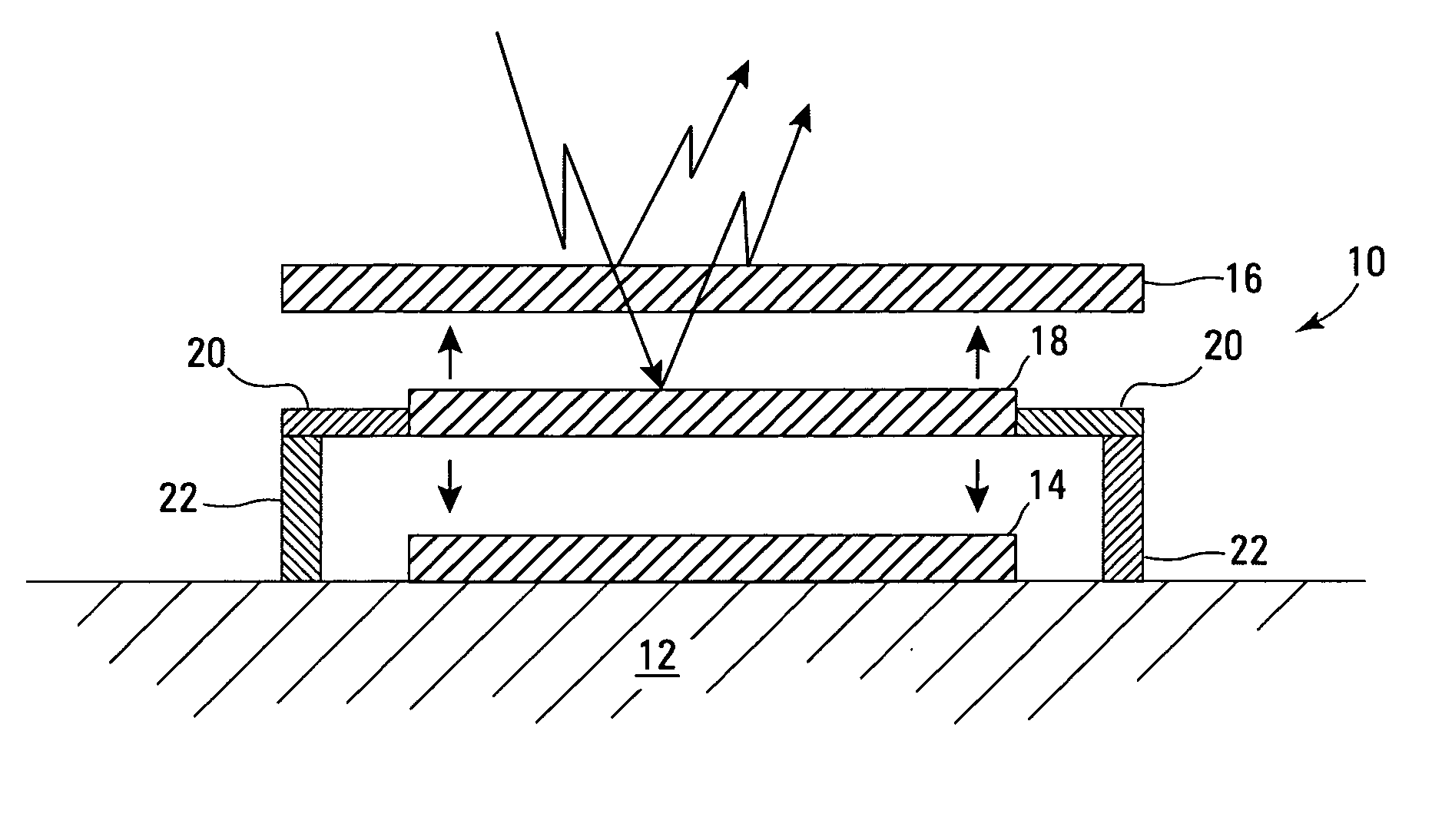
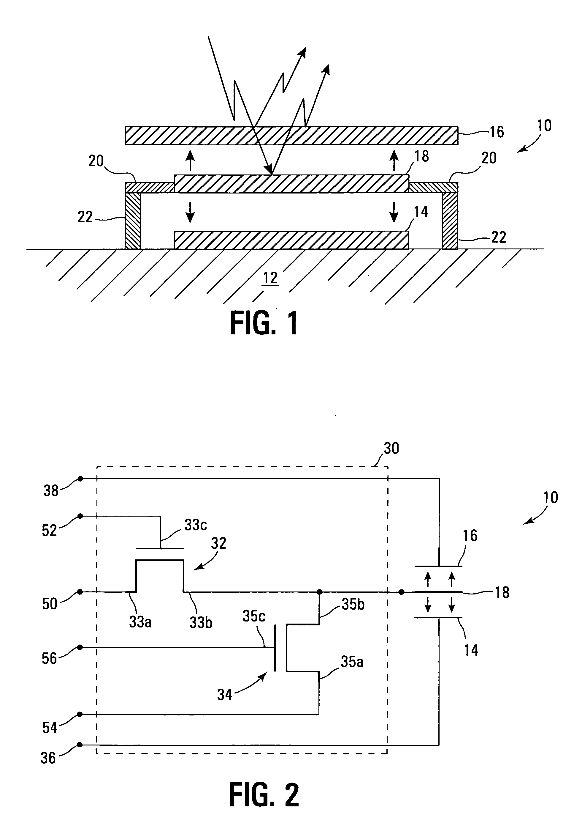
[0012]FIG. 1 illustrates one embodiment of a MEMS 10 adapted to be operated so as to overcome the effects of stiction. MEMS 10 is formed on a substrate 12 and includes a bottom capacitor plate ...


PUM


Abstract

A circuit and method for controlling a micro-electromechanical system is herein disclosed. In one embodiment of a micro-electromechanical system having top and bottom capacitor plates with a pixel plate movably positioned therebetween, a release voltage sufficient to overcome stiction forces adhering the pixel plate to one of the capacitor plates is applied to the pixel plate to cause the pixel plate to be attracted to the pixel plate opposite the capacitor plate to with which the pixel plate is in contact. After the pixel plate has moved a predetermined distance away from the capacitor plate to which it had been adhered by stiction forces, the release voltage is removed. Thereafter, an positional voltage is applied to the pixel plate to move the pixel plate to a desired location between the capacitor plates. Release and positional voltages are coupled to and decoupled from the pixel plate by one or more switching mechanisms.

Description

TECHNICAL FIELD OF THE INVENTION [0001] The present invention relates to a circuit and control method for overcoming stiction in micro-electromechanical systems. BACKGROUND OF THE INVENTION [0002] Micro-electromechanical systems (MEMS) are systems which are developed using thin film technology and which include both electrical and micro-mechanical components. MEMS devices are used in a variety of applications such as optical display systems, pressure sensors, flow sensors and charge control actuators. MEMS devices use electrostatic force or energy to move or monitor the movement of micro-mechanical electrodes which can store charge. In one type of MEMS device, to achieve a desired result, a gap distance between the electrodes is controlled by balancing an electrostatic force and a mechanical restoring force. Digital MEMS devices use two gap distances, while analog MEMS devices use multiple gap distances. [0003] MEMS functionality is often degraded or even destroyed by a phenomenon c...

Claims


Application Information

Patent Timeline
Patent Type & Authority Applications(United States)
IPC IPC(8): G09G3/34
CPCB81C1/00968G02B26/001G09G3/2011G09G3/3466G09G2310/0251G09G2310/06G09G2320/0693
Inventor MARTIN, ERICPIEHL, ARTHUR R.
Owner HEWLETT PACKARD DEV CO LP
Why Eureka
Try Eureka