Mobile antenna mounted on a vehicle body
a technology for mobile antennas and vehicle bodies, which is applied in the direction of antennas, antenna details, antenna adaptation in movable bodies, etc., can solve the problems of reducing the reception efficiency of mobile antennas with respect to radio waves transmitted from the rear side of the vehicle, affecting the diversity of the system, and affecting the reception efficiency of mobile antennas
- Summary
- Abstract
- Description
- Claims
- Application Information
AI Technical Summary
Problems solved by technology
Method used
Image
Examples
first embodiment
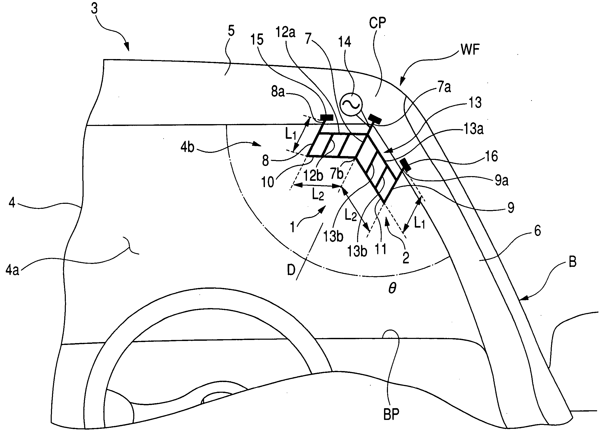
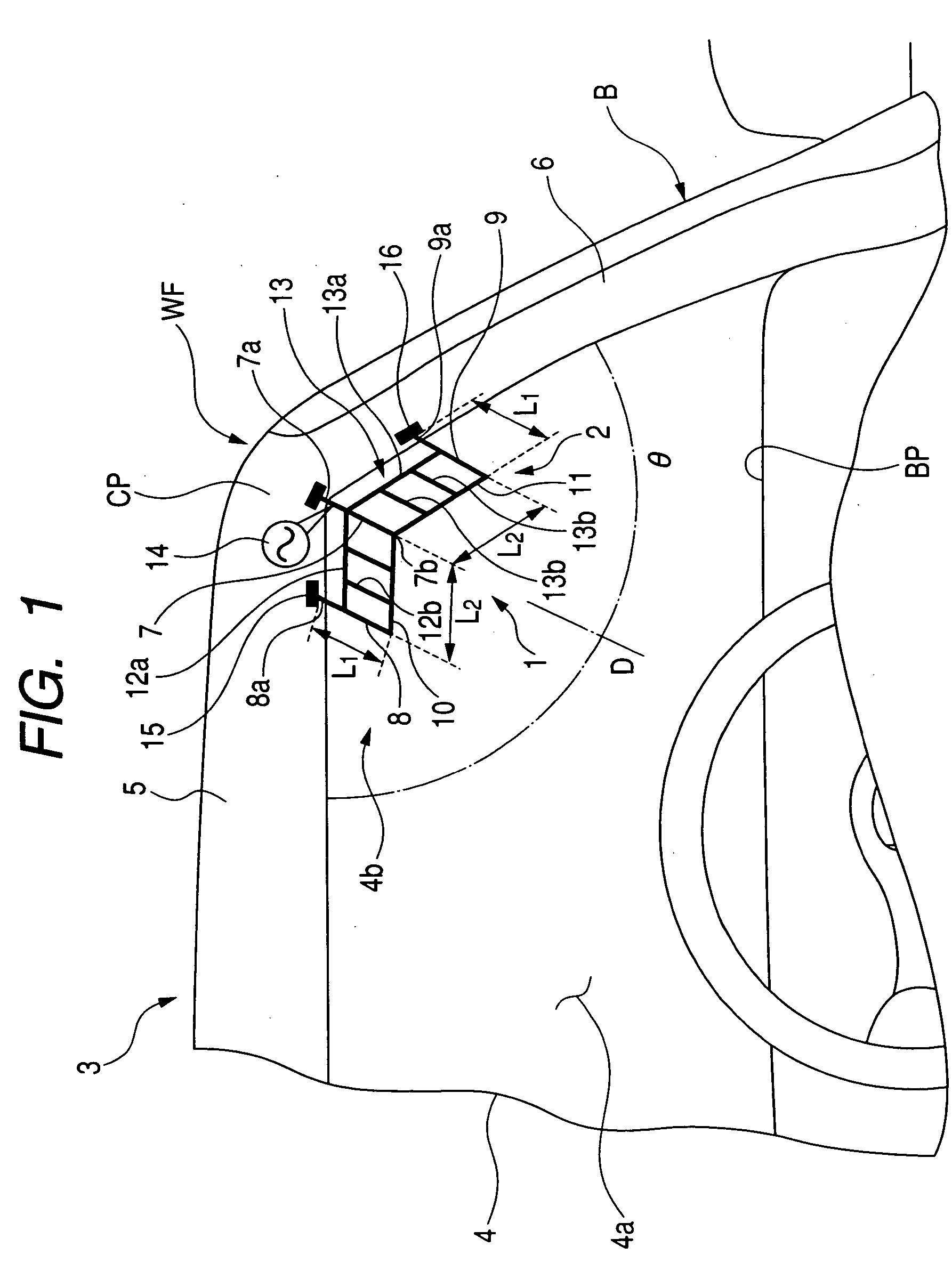
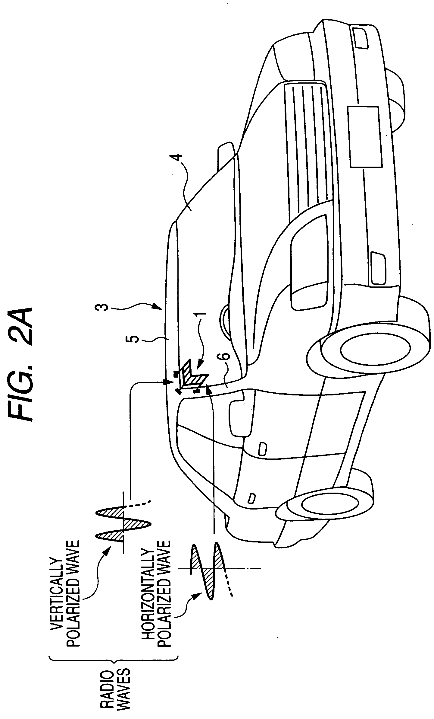
[0073]FIG. 1 schematically illustrates a mobile antenna 1 according to a first embodiment of the present invention, which is mounted on an electrically-conductive body frame B of a vehicle, such as a passenger car, 3.
[0074] As illustrated in FIG. 1, the mobile antenna 1 is formed as, for example, a film antenna. Specifically, the mobile antenna 1 is provided with an antenna element 2, which can be produced from any electrically conductive member, such as a wire, a rod, a tube, or the like, and formed in a loop. The antenna element 2 is, for example, attached on an inner surface 4a of a rectangular front windshield (windshield glass) 4 through, for example, a film member (not shown). The film member can be made of, for example, a transparent insulation material, such as a transparent resin, and can have a substantially similar shape as the antenna element 2.
[0075] The antenna element 2 is located at, for example, the upper-right corner portion 4b of the inner surface 4a of the fron...
second embodiment
[0263] A second embodiment of the present invention will be described with reference to FIGS. 19 to 21. Note that descriptions of elements related to the second embodiment, which are substantially the same as those related to the first embodiment, are omitted so that remaining elements related to the second embodiment, which are different from the remaining elements related to the first embodiment, will be described.
[0264]FIG. 19A schematically illustrates a mobile antenna 111 according to a second embodiment of the present invention, which is mounted on the body frame B of the vehicle 3.
[0265] The mobile antenna 111 is provided with an antenna element 112 formed in a loop. The antenna element 112 is located at, for example, the upper-right corner portion 4b of the inner surface 4a of the front windshield 4.
[0266] The antenna element 112 has a first linear portion 112a, a second linear portion 112b, and a third linear portion 112c.
[0267] The first linear portion 112a has one end...
third embodiment
[0318] A third embodiment of the present invention will be described with reference to FIGS. 22A to 22C. Note that descriptions of elements related to the third embodiment, which are substantially the same as those related to the first and second embodiments, are omitted so that remaining elements related to the third embodiment, which are different from the remaining elements related to the first and second embodiments, will be described.
[0319]FIG. 22A schematically illustrates a mobile antenna 201 according to a third embodiment of the present invention, which is mounted on the body frame B of the vehicle 3.
[0320] The mobile antenna 201 is provided with a linear antenna element 202 with one opening end 202b. The linear antenna element 202 is located at, for example, the upper-right corner portion 4b of the inner surface 4a of the front windshield 4.
[0321] The linear antenna element 202 is arranged along the center direction 1) of the corner angle θ formed by the front edge of t...
PUM
 Abstract
Description
Claims
Application Information
 - R&D
- Intellectual Property
- Life Sciences
- Materials
- Tech Scout
- Unparalleled Data Quality
- Higher Quality Content
- 60% Fewer Hallucinations
Browse by: Latest US Patents, China's latest patents, Technical Efficacy Thesaurus, Application Domain, Technology Topic, Popular Technical Reports.
© 2025 PatSnap. All rights reserved.Legal|Privacy policy|Modern Slavery Act Transparency Statement|Sitemap|About US| Contact US: help@patsnap.com


