Antenna device for portable terminal

Inactive Publication Date: 2006-05-11
SAMSUNG ELECTRONICS CO LTD
View PDF4 Cites 15 Cited by
  • Summary
  • Abstract
  • Description
  • Claims
  • Application Information

AI Technical Summary

Benefits of technology

[0014] Another object of the present invention is to provide an antenna device for a portable terminal, configured such th

Problems solved by technology

However, antenna devices adopted by the conventional portable terminals have the following disadvantages.
Moreover, when a portable terminal with an external antenna drops, the external antenna is more likely to be damaged.
Furthermore

Method used


Image

  • Antenna device for portable terminal
  • Antenna device for portable terminal
  • Antenna device for portable terminal

Examples


Embodiment Construction

[0025] A preferred embodiment of the present invention will be described hereinbelow with reference to the accompanying drawings. In the drawings, the same or similar elements are denoted by the same reference numerals even though they are depicted in different drawings. In the following description, well-known functions or constructions are not described in detail since they would obscure the invention in unnecessary detail.

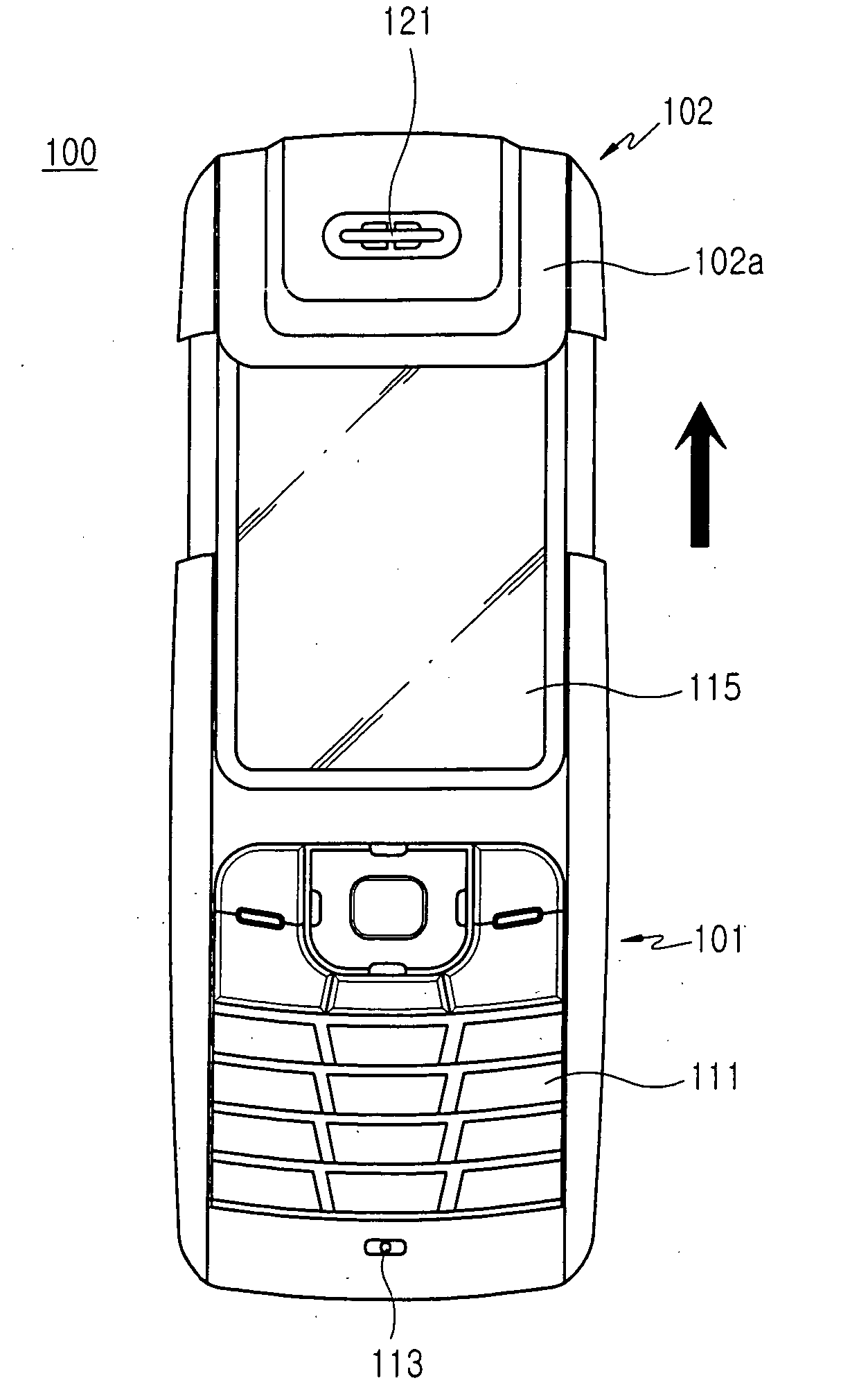
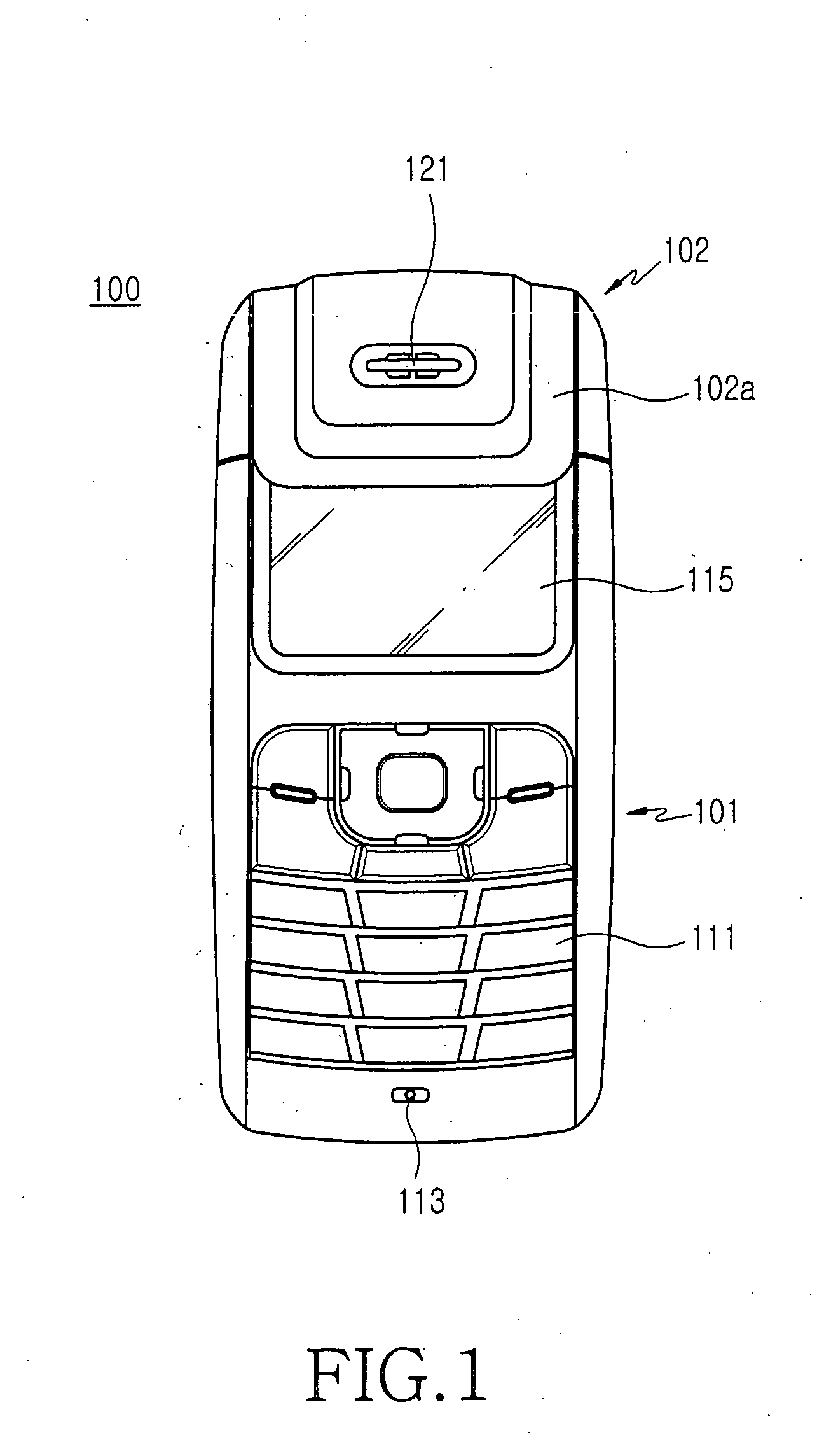
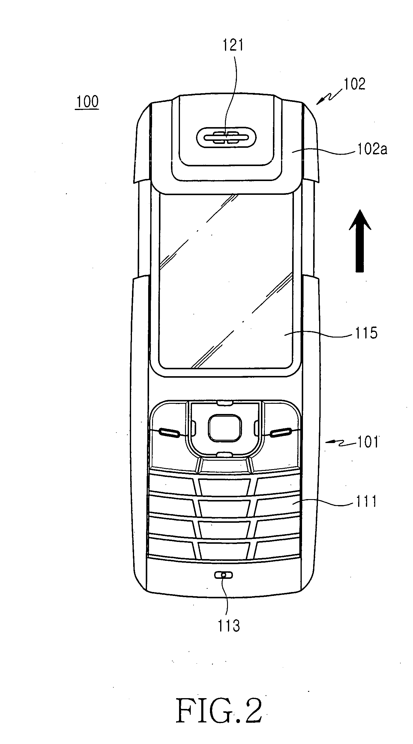
[0026]FIG. 1 is a front view illustration of a portable terminal 100 including an antenna device according to a preferred embodiment of the present invention, FIG. 2 is a front view illustrating a state after a second housing 102 of the portable terminal 100 shown in FIG. 1 is slidingly moved, and FIGS. 3 and 4 are rear views of the portable terminal 100 shown in FIGS. 1 and 2, respectively.

[0027] As shown in FIGS. 1 through 4, the portable terminal 100 includes a bar shaped first housing 101, in the front of which a keypad 111, a mouthpiece 113, and a display...


PUM


Abstract

Provided is an antenna device for a portable terminal including a first housing and a second housing assembled with the first housing so as to slidingly move on the first housing. The antenna device includes an antenna pattern installed on an inner surface of the second housing; and at least one connecting terminal, which is installed on the outer surface of the first housing and is sliding by connected to the antenna pattern, wherein the second housing is assembled with the first housing to at least partially cover the first housing. The antenna device has few parts and has a simple structure, thus simplifying manufacture and reducing.

Description

PRIORITY [0001] This application claims priority under 35 U.S.C. § 119 to an application entitled “Antenna Device for Portable Terminal” filed in the Korean Intellectual Property Office on Oct. 26, 2004 and assigned Ser. No. 2004-85874, the contents of which are incorporated herein by reference.BACKGROUND OF THE INVENTION [0002] 1. Field of the Invention [0003] The present invention relates generally to portable terminals including digital communication devices such as cellular phones, personal digital assistants (PDAs), hand held phones (HHPs), camera phones, game phones, and Internet phones, and in particular, to an antenna device for a portable terminal, of which transmission / reception sensitivity is adjusted according to sliding movement on the portable terminal. [0004] 2. Description of the Related Art [0005] The term portable terminal commonly refers to an electronic device with which a user can perform wireless communications. The design trend of portable terminals is geared ...

Claims


Application Information

Patent Timeline
IPC IPC(8): H01Q1/24
CPCH01Q1/243H01Q1/38H01Q9/0407H01Q7/00H04M1/0237
Inventor KIM, DONG-HWANKIM, JINUCHOI, WAN-JIN
Owner SAMSUNG ELECTRONICS CO LTD
Why Eureka
Try Eureka