Artificial knee joint

a knee joint and artificial technology, applied in the field of artificial knee joints, can solve the problems of complex structure of disclosed artificial knee joints, inability of artificial knee joints to adjust the resistance to axle rotation, and the wearer of prostheses to fall down

Inactive Publication Date: 2011-11-03
CHEN CHIEN WEN +1
View PDF7 Cites 18 Cited by
  • Summary
  • Abstract
  • Description
  • Claims
  • Application Information

AI Technical Summary

Benefits of technology

[0006]Therefore, an object of the present invention is to provide an artificial knee joint capable of providing resistance to relative rotation between a lower joint member and an axle thereof.
[0007]Another object of the present invention is to provide an artificial knee joint capable of adjusting sensitivity of resistance to relative rotation between a lower joint member and an axle thereof.
[0008]A further object of the present invention is to provide an artificial knee joint that can suit the individual weight of different prosthesis wearers.

Problems solved by technology

When a prosthesis wearer walks on an uneven surface and wants to stop walking, the prosthesis wearer will fall down if the artificial knee joint is unable to resist rotation.
However, the structure of the disclosed artificial knee joint is complicated.
Further, the disclosed artificial knee joint is unable to adjust sensitivity of resistance to rotation of the axle, and is not configured to suit the individual weight of different prosthesis wearers.

Method used


Image

  • Artificial knee joint
  • Artificial knee joint
  • Artificial knee joint

Examples


Embodiment Construction

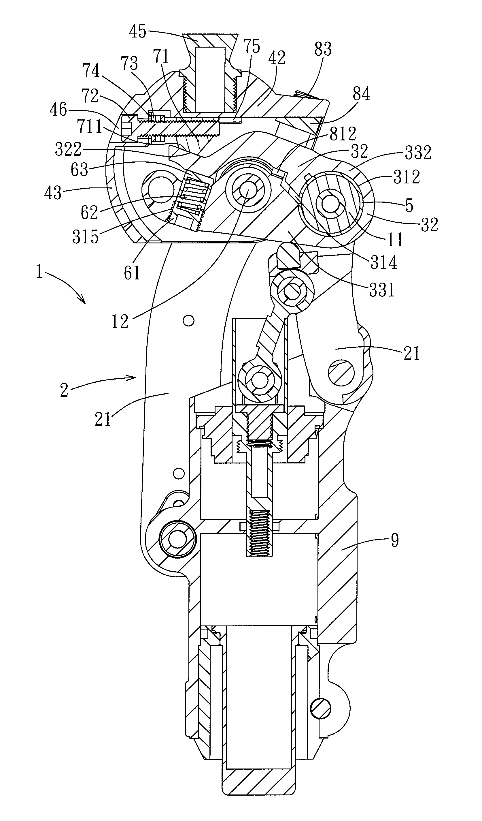
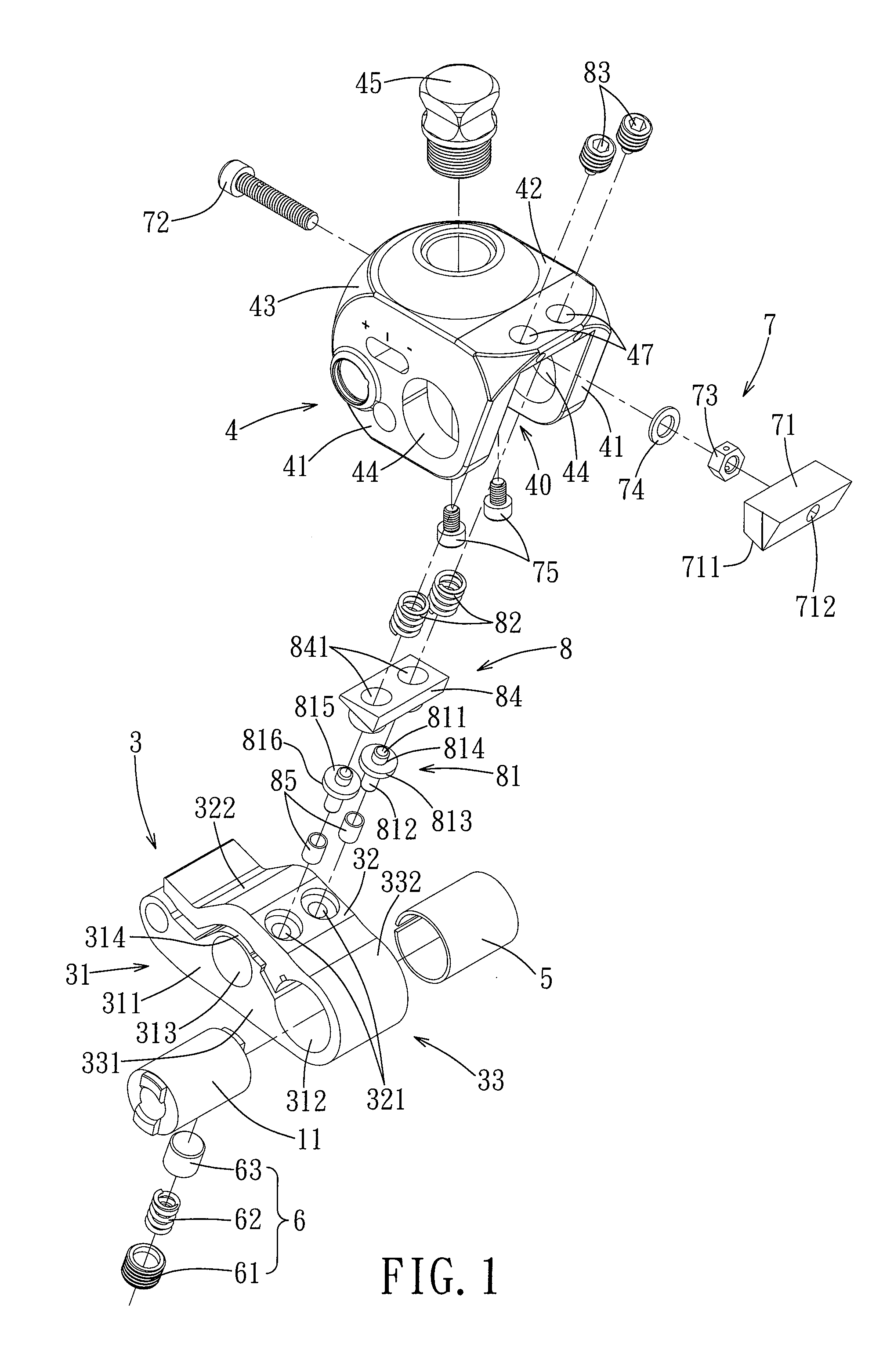
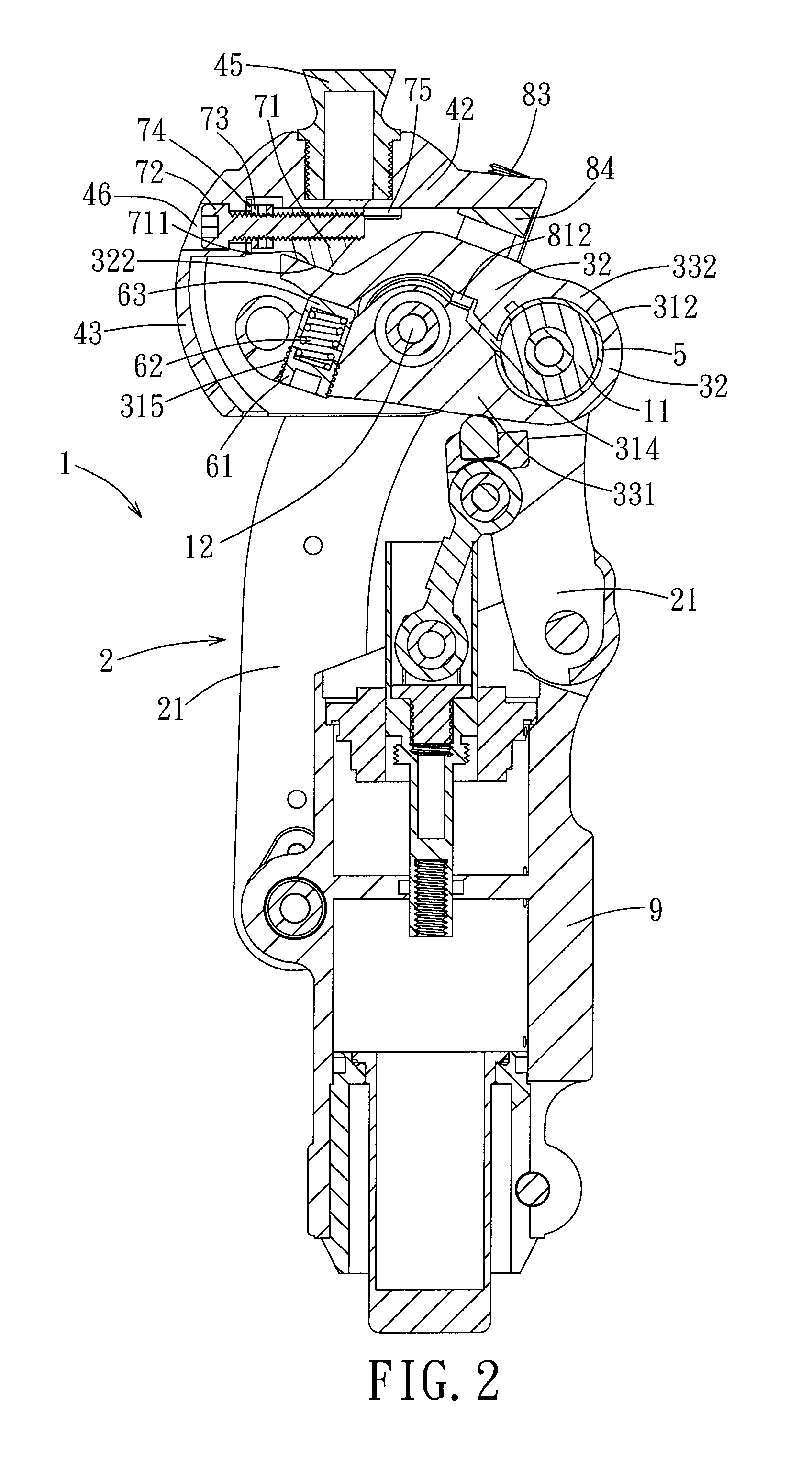
[0017]Referring to FIGS. 1 and 2, the preferred embodiment of an artificial knee joint 1 of the present invention is adapted for connecting a prosthetic thigh (not shown) to a prosthetic lower leg (not shown). The artificial knee joint 1 includes a link assembly 2, a lower joint member 3, a kneecap member 4, a C-shaped sleeve 5, a biasing assembly 6, a press member 7, and a lower seat 9.

[0018]The link assembly 2 includes four links 21, but only two of the links 21 are visible in FIG. 2 due to the angle of view. The kneecap member 4 is adapted to be connected to the prosthetic thigh, and is disposed above and pivoted to the lower joint member 3. The lower seat is disposed under the lower joint member 3 for connection of the prosthetic lower leg, and is connected to the lower joint member 3 by the links 21 of the link assembly 2. The sleeve 5 and the biasing assembly 6 are disposed within the lower joint member 3, and the press member 7 is mounted to the kneecap member 4 and between t...


PUM


Abstract

An artificial knee joint includes a lower joint member, an axle, a kneecap member, and a press member. The lower joint member is formed with a horizontally extending axle-receiving hole, and a clearance extending from and in spatial communication with the axle-receiving hole. The axle is received in the axle-receiving hole. The kneecap member is pivoted to the lower joint member, and is adapted to be connected to a prosthetic thigh. The press member is mounted to the kneecap member for pressing the lower joint member when the kneecap member pivots in a direction relative to the lower joint member. Therefore, the clearance and the axle-receiving hole are constricted to result in tightened connection between the lower joint member and the axle and resistance to relative rotation between the lower joint member and the axle.

Description

BACKGROUND OF THE INVENTION[0001]1. Field of the Invention[0002]The present invention relates to an artificial knee joint, more particularly to an artificial knee joint capable of providing resistance to relative rotation between a lower joint member and an axle thereof.[0003]2. Description of the Related Art[0004]In a prosthesis for a femur amputee, an artificial knee joint for connecting a prosthetic thigh to a prosthetic lower leg is particularly important. When a prosthesis wearer walks on an uneven surface and wants to stop walking, the prosthesis wearer will fall down if the artificial knee joint is unable to resist rotation.[0005]Taiwanese Utility Model No. M284363 discloses an artificial knee joint including a mechanism for preventing the prosthesis wearer from falling down. The disclosed artificial knee joint includes an axle received in an axle-receiving hole that has an inner wall formed with a plurality of grooves parallel to the axle. Each of the grooves has a narrow po...

Claims


Application Information

Patent Timeline
Patent Type & Authority Applications(United States)
IPC IPC(8): A61F2/64
CPCA61F2/644A61F2/68A61F2002/502A61F2002/503A61F2005/016A61F2002/5083A61F2002/6818A61F2002/6854A61F2002/5075
Inventor CHEN, CHIEN-WENCHEN, CHIEN-CHENG
Owner CHEN CHIEN WEN
Why Eureka
Try Eureka