Optical fiber based polymer core sensor

a technology of optical fiber and polymer core, applied in the field of optical fiber sensors, can solve the problems of ri sensors based on fiber gratings that are usually expensive, the interference pattern shifts, and the sensor system is complicated, and achieves the effects of high thermo-optic coefficient, simple fabrication techniques, and improved sensitivity

Inactive Publication Date: 2010-05-06
BOARD OF RGT THE UNIV OF TEXAS SYST
View PDF7 Cites 19 Cited by
  • Summary
  • Abstract
  • Description
  • Claims
  • Application Information

AI Technical Summary

Benefits of technology

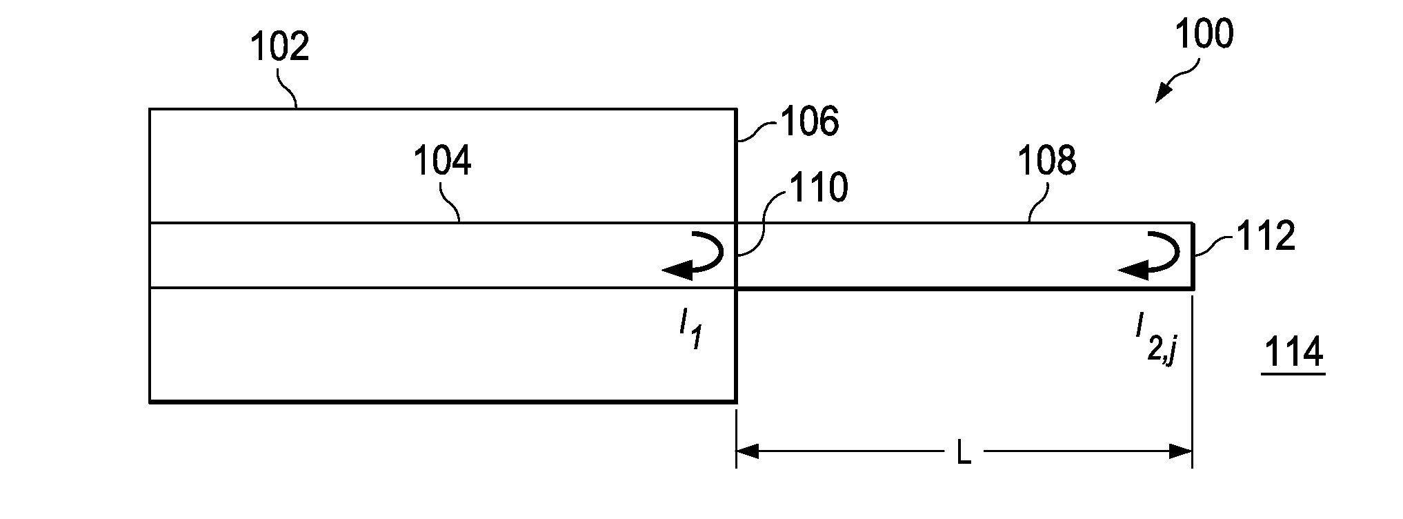
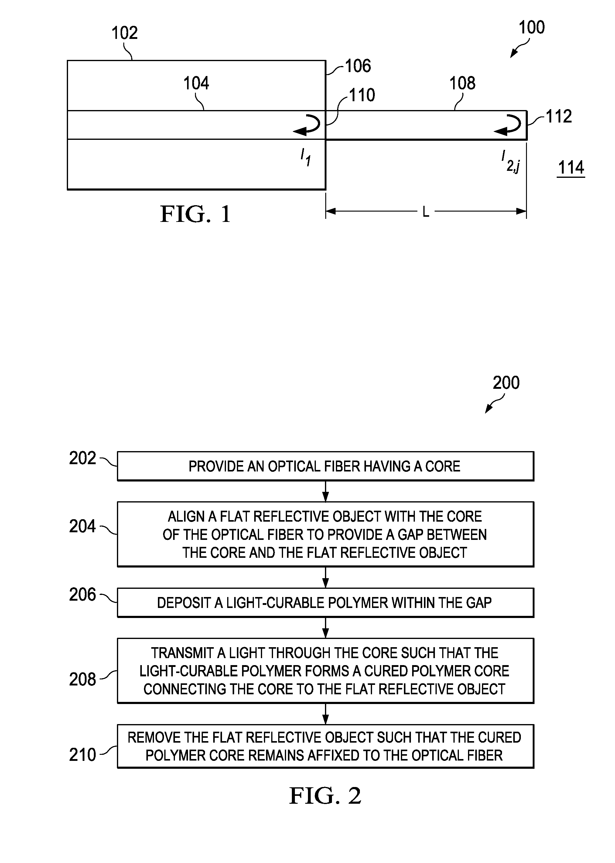
[0012]The fabrication, analysis, and evaluation of a compact refractive index (RI) and temperature sensor using a micro-sized polymer core fabricated at the end of an optical fiber that uses low-cost commercial products and simplified fabrication techniques is described herein. The refractive index of the polymer used is different from that of the optical fiber so that a part of the light traveling in the optical fiber can be reflected at the fiber / polymer interface. The polymer tip serves as a Fabry-Perot interferometric cavity so that a phase shift is introduced to the light propagating in it when the RI of the surrounding medium changes and thus causes a fringe shift in the interferometric fringe spectrum. With respect to temperature measurements, the optical path traveled by the light coupled into the polymer tip changes with the ambient temperature due to the combination of thermal expansion and thermo-optic effect. Because the polymer tip has a high thermo-optic coefficient compared to silica, the temperature sensitivity of the sensor when used for temperature measurements is higher than most of the reported sensors that works under the same principle. The sensitivity of the sensor can be adjusted or modified by changing the length or shape of the polymer tip length and / or tailoring the properties of the polymer material. Moreover, the present invention does not require the use of cladding materials, dyes, etching or complex fabrication techniques. As a result, the present invention provides greater sensitivity and overcomes many of the limitations of other optical fiber based sensors.

Problems solved by technology

When these two arms are combined to generate an interference pattern, a change in the external RI alters the optical path length of the sensing arm and thus causes a shift in the interference pattern.
Interferometric RI sensors often require a mechanism to split the incoming light into two arms, resulting in a more complicated sensor system.
RI sensors based on fiber grating are usually expensive because of the stringent grating fabrication processes.
On the other hand, IFPI sensors are usually more difficult and expensive to fabricate [13].
However, thin film mirrors can easily be damaged.
Besides, it is difficult to control the film thickness and flatness with precision.
But in order to fabricate an IFPI sensor with this configuration, the ends of fibers have to be polished with four different polishing films beforehand to prevent large power losses, which is a long and tedious process [16].

Method used


Image

  • Optical fiber based polymer core sensor
  • Optical fiber based polymer core sensor
  • Optical fiber based polymer core sensor

Examples


Embodiment Construction

[0035]While the making and using of various embodiments of the present invention are discussed in detail below, it should be appreciated that the present invention provides many applicable inventive concepts that can be embodied in a wide variety of specific contexts. The specific embodiments discussed herein are merely illustrative of specific ways to make and use the invention and do not delimit the scope of the invention. The discussion herein relates primarily to optical fiber based polymer core sensors for refractive index and temperature sensor, but it will be understood that the concepts of the present invention are applicable to any optical fiber based sensors for strain measurement, distance measurement, toxin detection, biological agent detection, chemical process monitoring, pH measurement, analyte measurement, etc.

[0036]To facilitate the understanding of this invention, a number of terms are defined below. Terms defined herein have meanings as commonly understood by a pe...


PUM

PropertyMeasurementUnit
wavelengthaaaaaaaaaa
lengthaaaaaaaaaa
diameteraaaaaaaaaa

Abstract

An optical fiber based polymer core sensor includes an optical fiber having a core and an end having a cured polymer core affixed to the core of the optical fiber. The cured polymer core extends outward from the end of the optical fiber and has a diameter approximately equal to the core of the optical fiber. Note the cured polymer core can be substantially cylindrical, tapered or geometrically shaped. The optical fiber based polymer core sensor can be used to measure a temperature, measure a strain, measure a distance, measure a refractive index, detect or measure an analyte, detect a toxin, detect a biological agent, monitor a chemical process, or a combination thereof

Description

STATEMENT OF FEDERALLY FUNDED RESEARCH[0001]This invention was made with U.S. Government support under Contract No. CMS-0650716 awarded by the NSF. The government has certain rights in this invention.[0002]CROSS-REFERENCE TO RELATED APPLICATIONS[0003]This application claims benefit of U.S. Provisional application Ser. No. 61 / 094,467 filed on Sep. 5, 2008, which is incorporated herein by reference in its entirety.FIELD OF THE INVENTION[0004]The present invention relates generally to the field of optical fiber sensors and, more particularly, to an optical fiber based polymer core sensor.BACKGROUND OF THE INVENTION[0005]Without limiting the scope of the invention, its background is described in connection with optical fiber sensors and their applications.[0006]Most optical fiber biochemical sensors are based on measuring the RI of bio / chemical liquids using various sensing schemes such as interferometry [1], fiber gratings [2-5], and specialty fibers [7-11]. Interferometer-based RI sen...

Claims


Application Information

Patent Timeline
Patent Type & Authority Applications(United States)
IPC IPC(8): G01K11/32G02B6/10G02B1/12
CPCG01D5/35303G01K11/3213G01N21/7703G01N2021/772G01N2021/7773G02B6/02033G01D5/35312
Inventor HUANG, HAIYINGMAJUMDAR, AYAN
Owner BOARD OF RGT THE UNIV OF TEXAS SYST
Why Eureka
Try Eureka