Tracking system for flat mobile antenna

a tracking system and antenna technology, applied in direction finders, antennas, antenna adaptation in movable bodies, etc., can solve the problems of low price, high cost, significant error, etc., and achieve the effect of improving the average signal-to-noise ratio (snr), reducing the impact of gyroscope errors, and improving the speed of gyroscope errors correction

Active Publication Date: 2006-12-07
GILAT SATELLITE NETWORKS
View PDF9 Cites 13 Cited by
  • Summary
  • Abstract
  • Description
  • Claims
  • Application Information

AI Technical Summary

Benefits of technology

[0006] An objective of the present invention is to provide a tracking system with low price, which keeps the antenna beam in the direction towards the selected satellite, regardless of the movement of the vehicle, where it is mounted. It is also desirable that the antenna orientation is kept even during temporary interruptions of the reception due to obstacles non-transparent to radio waves like buildings, trees, tunnels, bridges, hills, etc.
[0019] It is advisable in this case that the antenna beam is controlled in such a way, that it keeps staying for a longer period in the fixed position, which is closest to the direction towards the satellite, while it is switched to neighboring fixed positions for much shorter intervals, thus keeping the average signal strength as high as possible.
[0023] The advantages of the tracking system according to the present invention are: using low-cost sensors, decreased impact of gyroscope errors on tracking error, improved speed of correction of gyroscope errors using measured strength of received signal in comparison with antennas with mechanical-only beam movement, improved average signal-to-noise ratio (SNR) due to longer periods when the antenna beam is kept close to direction toward the satellite.

Problems solved by technology

They feature a low price, but suffer by significant error, produced by temperature change, linear acceleration and other factors on their offset and scale factor.
The disadvantage of the mentioned system is the requirement for additional phase shifters, which makes it more complex and expensive.
Moreover, the tracking system does not perform an estimation of gyroscope errors, hence, the antenna may lose its direction shortly after the signal path is hidden by an obstacle.
Due to big latencies of mechanical driving system the averaging intervals of such system are relatively large, which means that gyroscope offset corrections follow with big delays.
Moreover, such a system can be affected by signal fluctuations due to small obstacles which don't completely interrupt the signal, but only decrease its strength for a short time.
This system does not use orientation sensors, that's why it cannot keep its orientation when the signal reception is interrupted by an obstacle.

Method used


Image

  • Tracking system for flat mobile antenna
  • Tracking system for flat mobile antenna
  • Tracking system for flat mobile antenna

Examples


Embodiment Construction

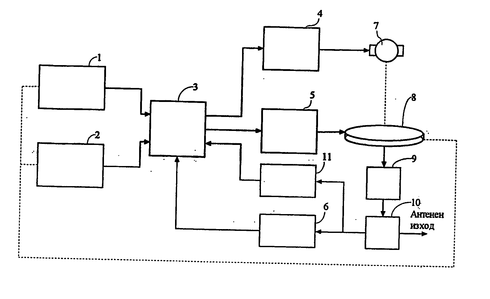
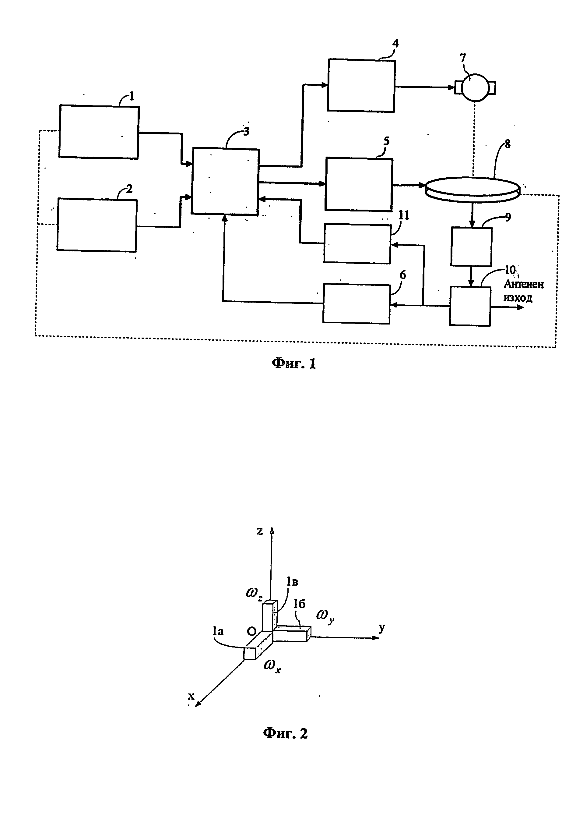
[0031] One possible variant of implementation of tracking system according to the present invention is shown at FIG. 1. It comprises sensors for angular velocity (gyroscopes) 1, inclination sensors 2, control block 3, driving block 4, motor 7, block for electronic beam control 5, antenna panel with electronic beam steering 8, down-converter 9, directional coupler 10, decoding block 11, and RF detector 6.

[0032] The outputs of gyroscope sensors 1 and outputs of inclination sensors 2 are fed to control block 3, as well as the outputs of RF detector 6 and block for decoding of received signal 11 are. One of the outputs of the control block 3 is fed to the input of the block for electronic beam control 5, while the other output is fed to the input of the driving block 4, which output is fed to the motor 7, which moves the antenna panel 8. The antenna panel 8 output is fed to the input of the down-converter 9, which output is connected to inputs of RF detector 6 and the decoding block 11...


PUM


Abstract

Tracking system for flat mobile antenna, which includes: sensors for angular velocity (1), which sense the rotation of the antenna around their axes; sensors, sensing the orientation of the antenna according to vertical axis (2); control block (3), which calculates necessary corrections of the direction of antenna beam and which is connected to outputs of sensors (1, 2) and with inputs of driving block (4) and beam control block (5); at least one motor (7), which changes the orientation of the antenna and which is connected to the output of driving block (4) and which drives the antenna panel (8); block for electronic beam steering (5), which is connected to antenna panel (8); power supply block, which converts the voltage from the electrical network of the vehicle into suitable values for providing of power supply of all blocks of the system.

Description

FIELD OF THE INVENTION [0001] The present invention relates to a tracking system for flat antenna with combined mechanical pointing for one axis and electronic beam steering for the other axis, which can be mounted on moving vehicles and platforms and which provides television, Internet and other communication signals, transmitted by satellites. PRIOR ART [0002] In order to receive signals from satellite, the antenna mounted on a moving vehicle should keep its orientation, so that its beam to be always directed toward the satellite. For this purpose antennas with mechanical or / and electronic beam steering are required, which work under control of a tracking system, which reacts to the changes of orientation of the vehicle (or directly of the antenna) and issues commands to motors or to block for electronic beam control to provide necessary corrections in beam direction. In most cases such tracking systems include sensors for angular velocity (rate gyroscopes), based on quartz, piezo...

Claims


Application Information

Patent Timeline
Patent Type & Authority Applications(United States)
IPC IPC(8): H01Q3/00G01S3/42H01Q1/32H01Q3/04H01Q3/26H01Q3/30
CPCG01S3/42H01Q1/3208H01Q3/30H01Q3/04H01Q3/2605H01Q1/325H01Q1/24H01Q1/32H01Q3/02H01Q3/08
Inventor IVANOV, IVANPRODANOV, HRISTOPANAYOTOV, VELISLAV
Owner GILAT SATELLITE NETWORKS
Why Eureka
Try Eureka