Arc resistant baffle for reducing arc-flash energy in an electrical enclosure

a technology of arc-flash energy and baffles, which is applied in the direction of insulated conductors, power cables, electrical apparatus casings/cabinets/drawers, etc., can solve the problem of providing an unimpeded path between the louvers for the flow of gas

Active Publication Date: 2007-05-03
ROCKWELL AUTOMATION TECH
View PDF20 Cites 69 Cited by
  • Summary
  • Abstract
  • Description
  • Claims
  • Application Information

AI Technical Summary

Benefits of technology

The invention provides a new way to vent hot gas from electrical enclosures. It can be used with different types of enclosures, including conventional sheet metal ones. It can be used on small or larger enclosures, and even in cases where a fan is used to expel air. The technique allows for better air circulation and helps prevent overheating.

Problems solved by technology

The present invention addresses the problem of managing hot gases that can result from faults and malfunctions in electrical enclosures. The challenge is to properly vent and cool the gases quickly, while still meeting industry standards for gas temperatures around the enclosure. Existing venting techniques can be expensive, destructive to the enclosure, or ineffective in managing arc flash faults. The invention provides an improved design for enclosures and techniques for venting gases that can meet industry standards for gas temperatures, while still allowing for conventional venting of the enclosure.

Method used


Image

  • Arc resistant baffle for reducing arc-flash energy in an electrical enclosure
  • Arc resistant baffle for reducing arc-flash energy in an electrical enclosure
  • Arc resistant baffle for reducing arc-flash energy in an electrical enclosure

Examples


Embodiment Construction

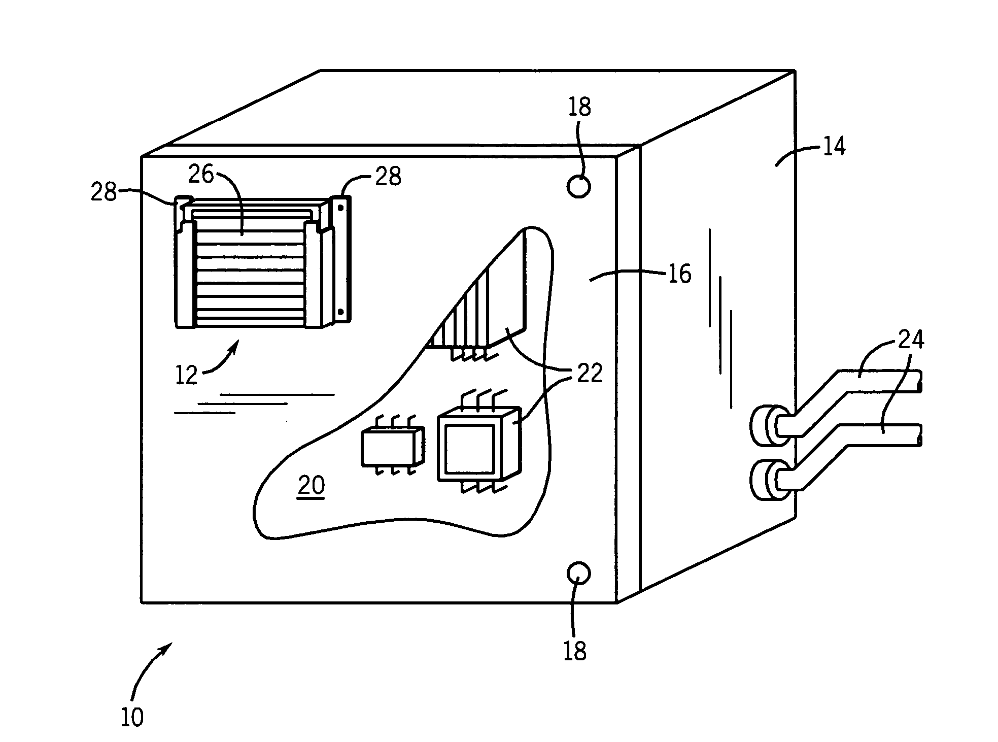
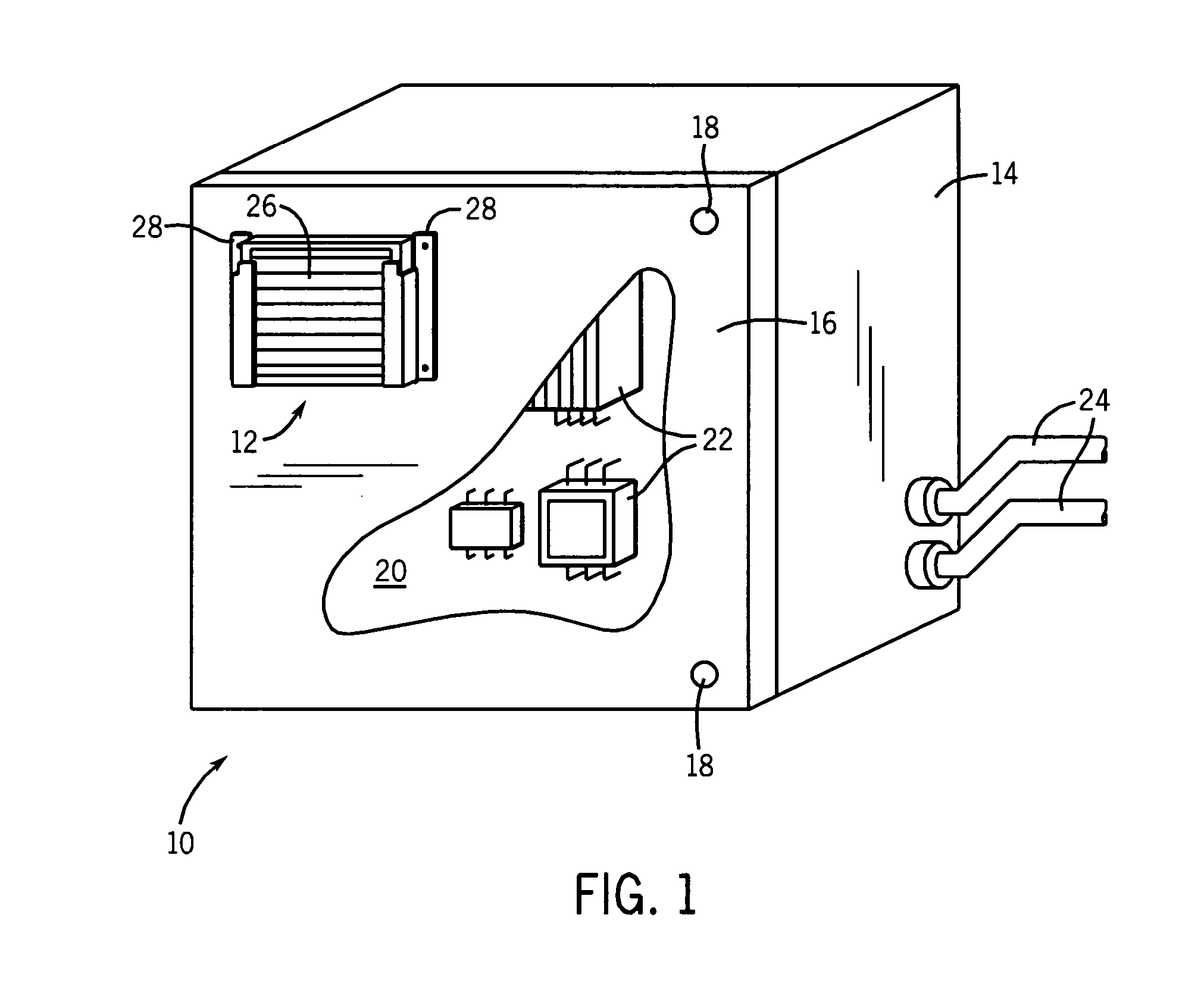
[0018] Turning now to the drawings, and referring first to FIG. 1, an enclosure 10 is illustrated in which a hot gas vent 12 is provided. The enclosure 10 may be any suitable type of electrical enclosure, such as an unsealed conventional sheet metal enclosure, but will typically be an enclosure in which normal venting is desired. The enclosure is formed of a shell 14 having an opening over which a door 16 may be closed. The door is typically hinged to the shell, and latches 18 permit the door to be secured in the closed position. When closed, the door 16 encloses with the shell 14 an interior volume 20 in which various electronic and electrical components 22 may be disposed. In a typical application, the components are mounted on one or more panels, and electrical wiring is terminated to the various components in accordance with the component and circuit designs. In presently contemplated embodiments, the components may be used to route single and three-phase alternating current pow...


PUM


Abstract

A venting system is described for use with electrical enclosures in which hot gasses may be generated by certain types of fault. The venting assembly may be mounted to a surface of the enclosure, such as adjacent to an aperture formed in the enclosure door. The vent assembly includes a series of louvers that divert all gasses flowing from the enclosure and provide no direct path for gas. The vent assembly thus provides unimpeded flow of hot gasses during a fault event to divert and cool the gasses before exiting the enclosure. The vent assembly may be configured as a cartridge-type insert mounted either inside or outside the enclosure.

Description


Claims


Application Information

Patent Timeline
Owner ROCKWELL AUTOMATION TECH
Why Eureka
Try Eureka