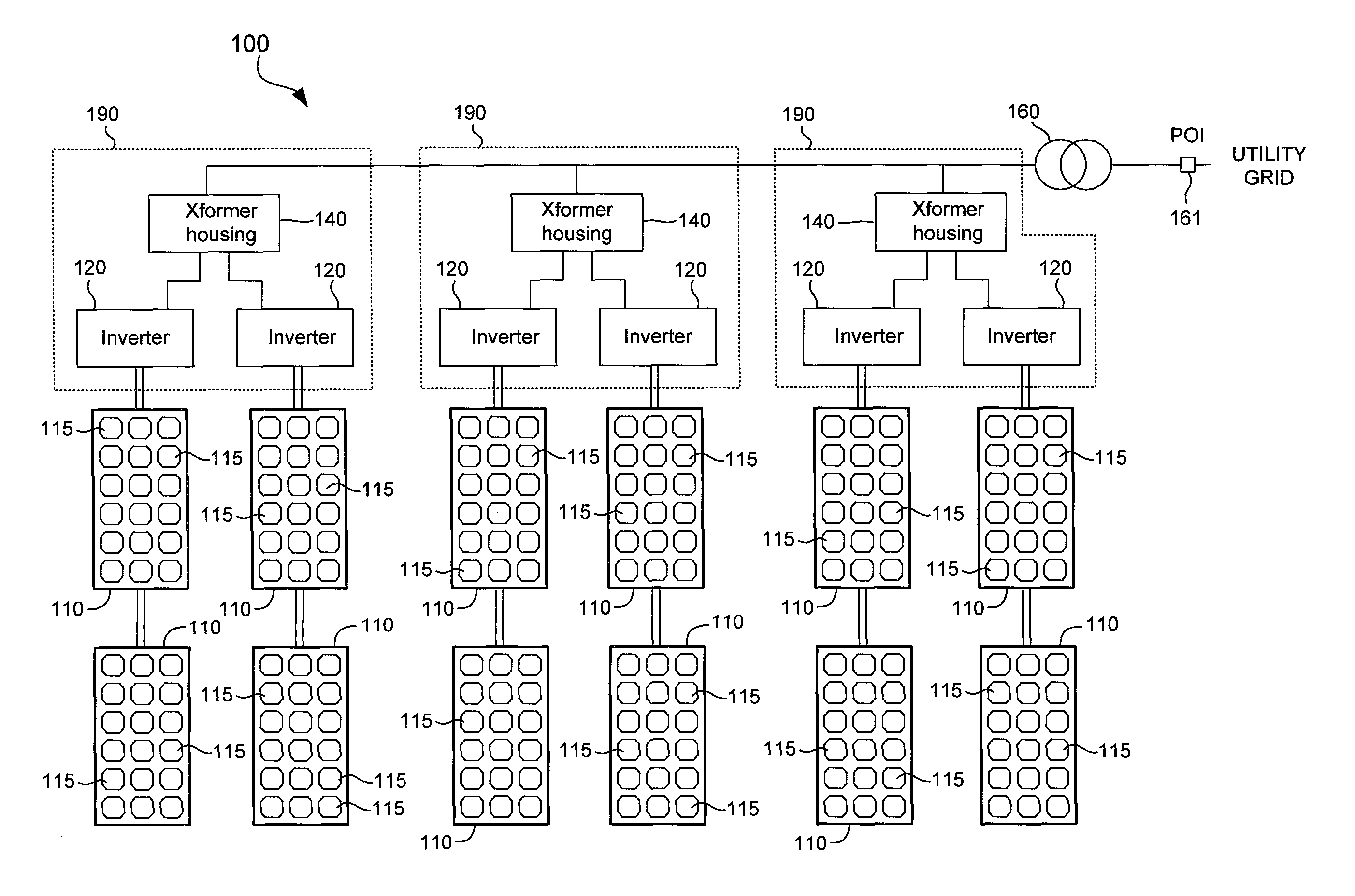
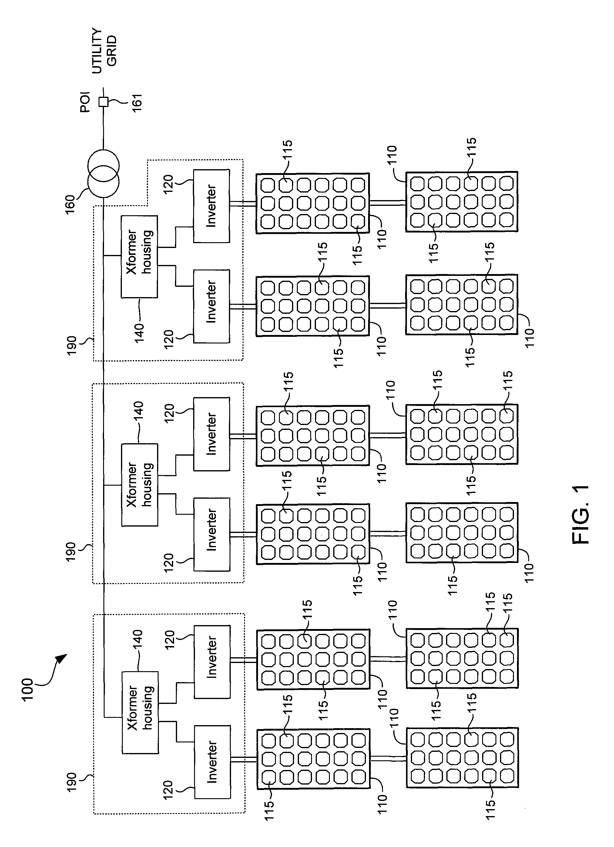
Mitigation of arc flash hazard in photovoltaic power plants

a photovoltaic power plant and arc flash technology, applied in the field of solar cells, can solve the problems of high arc flash energy within the inverter station, serious workplace hazards, and insufficient protection of workers at the inverter station, and achieve the effect of increasing the current rating

Active Publication Date: 2016-01-19
SOLAREDGE TECH LTD
View PDF21 Cites 23 Cited by
  • Summary
  • Abstract
  • Description
  • Claims
  • Application Information

AI Technical Summary

Problems solved by technology

Arc flash is a serious workplace hazard when working on inverters, such as during maintenance.
Mitigating arc-flash hazard in inverter stations poses several design challenges because the utility grid to which the inverter stations are connected serve as large fault current sources, leading to high arc-flash energies within the inverter stations during arc faults.
These solutions, however, may be difficult to achieve or inadequate to protect workers at inverter stations.
Certain protective devices are current limiting by design.
The potential problem of this solution is that below the fault current limit, the clearing time goes up significantly and, therefore, the incident energy level may exceed workable levels for a range of grid operating conditions of a photovoltaic power plant.
Therefore, increasing the working distance may not be practical in inverter stations.
A disadvantage of this solution, in particular for inverter stations, is that the level to which the current setting can be lowered is limited for normal operating conditions due to the need to coordinate the breaker tripping characteristics with equipment protection needs and avoiding normal short-term transient currents from tripping the breaker.
Other solutions for mitigating arc flash hazards in general include provision of bus differential protection and zone selective interlocking, the specific implementations of which are highly system-dependent, typically complex, and not cost effective.

Method used


Image

  • Mitigation of arc flash hazard in photovoltaic power plants
  • Mitigation of arc flash hazard in photovoltaic power plants
  • Mitigation of arc flash hazard in photovoltaic power plants

Examples


Embodiment Construction

[0026]In the present disclosure, numerous specific details are provided, such as examples of apparatus, components, and methods, to provide a thorough understanding of embodiments of the invention. Persons of ordinary skill in the art will recognize, however, that the invention can be practiced without one or more of the specific details. In other instances, well-known details are not shown or described to avoid obscuring aspects of the invention.

[0027]Conventional solutions to arc flash hazard described above are based on the premise that the solution should be common to both normal operational and maintenance conditions, i.e., the solution needs to guarantee the arc flash risk category is not higher than appropriate for safely performing commissioning and maintenance activities while ensuring the normal operating conditions are not impacted. However, a single setting of a protective device for both operation and maintenance does not guarantee the protective device can clear the fa...


PUM


Abstract

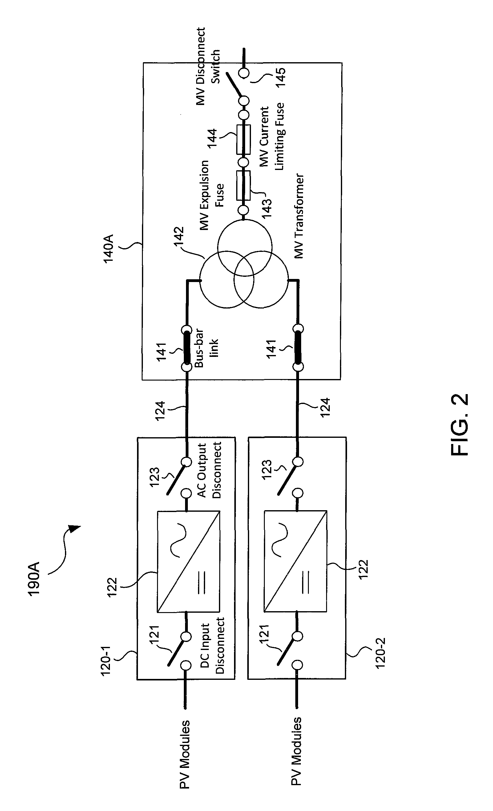
Arc flash mitigation devices are employed to protect personnel during maintenance of photovoltaic inverters. During normal operation, an alternating current (AC) output of a photovoltaic inverter is coupled to a low voltage winding of a step up transformer through a bus-bar (e.g., an electrically conductive interconnect), which has higher current rating than a fuse. During maintenance, the bus-bar is replaced with the fuse. The fuse may be employed in conjunction with a switch. The switch may be a disconnect switch that places the bus-bar in parallel with the fuse during normal operation, and decouples the bus-bar from the fuse during maintenance. The switch may also be a transfer switch that places either the bus-bar or the fuse in series with the AC output of the photovoltaic inverter and the low voltage winding of the step up transformer.

Description

TECHNICAL FIELD[0001]Embodiments of the subject matter described herein relate generally to solar cells. More particularly, embodiments of the subject matter disclosed herein relate to photovoltaic power plant operation and maintenance.BACKGROUND[0002]Photovoltaic power plants employ solar cells to convert solar radiation to electrical energy. Photovoltaic power plants also include photovoltaic inverters (“inverters”), which convert direct current (DC) generated by the solar cells to alternating current (AC) suitable for delivery to a point of interconnect with a utility grid through a network of transformers and transmission lines. Inverters are often employed in inverter stations that comprise multiple inverters connected to a single multiple-winding medium voltage step-up transformer, which in turn is connected to a medium voltage grid.[0003]Arc flash is a serious workplace hazard when working on inverters, such as during maintenance. Mitigating arc-flash hazard in inverter stati...

Claims


Application Information

Patent Timeline
Patent Type & Authority Patents(United States)
IPC IPC(8): H02H7/122H01L31/02H02M7/00H02J3/38H02M7/537H02H7/055
CPCH02H7/122H01L31/02021H02J3/383H02M7/00Y02E10/50H02J3/381H02J2300/24H02S40/36Y02E10/56
Inventor SIVAKUMAR, SESHADRILIAN, JIYONGKONALA, VENKAT REDDYBARR, DAVIDSIRISOORIYA, PRIYANTHAAHMAD, JACQUELINESPOKES, JASON
Owner SOLAREDGE TECH LTD
Why Eureka
Try Eureka