
Lighting fixture

a technology of light fixture and metal surface, which is applied in the direction of fixed installation, lighting and heating apparatus, lighting support devices, etc., can solve the problem of longer job, and achieve the effect of convenient attachment to the metallic surface, fast and convenient access, and fast and easy disengagement from the metal surfa

Inactive Publication Date: 2007-05-10
KENLY PRECISION INDAL
View PDF17 Cites 17 Cited by
  • Summary
  • Abstract
  • Description
  • Claims
  • Application Information

AI Technical Summary

Benefits of technology

[0005] The primary purpose of the present invention is to provide a lighting fixture that can be easily attached to metallic surface (e.g., refrigerator or metal door panel) for fast and convenient access.
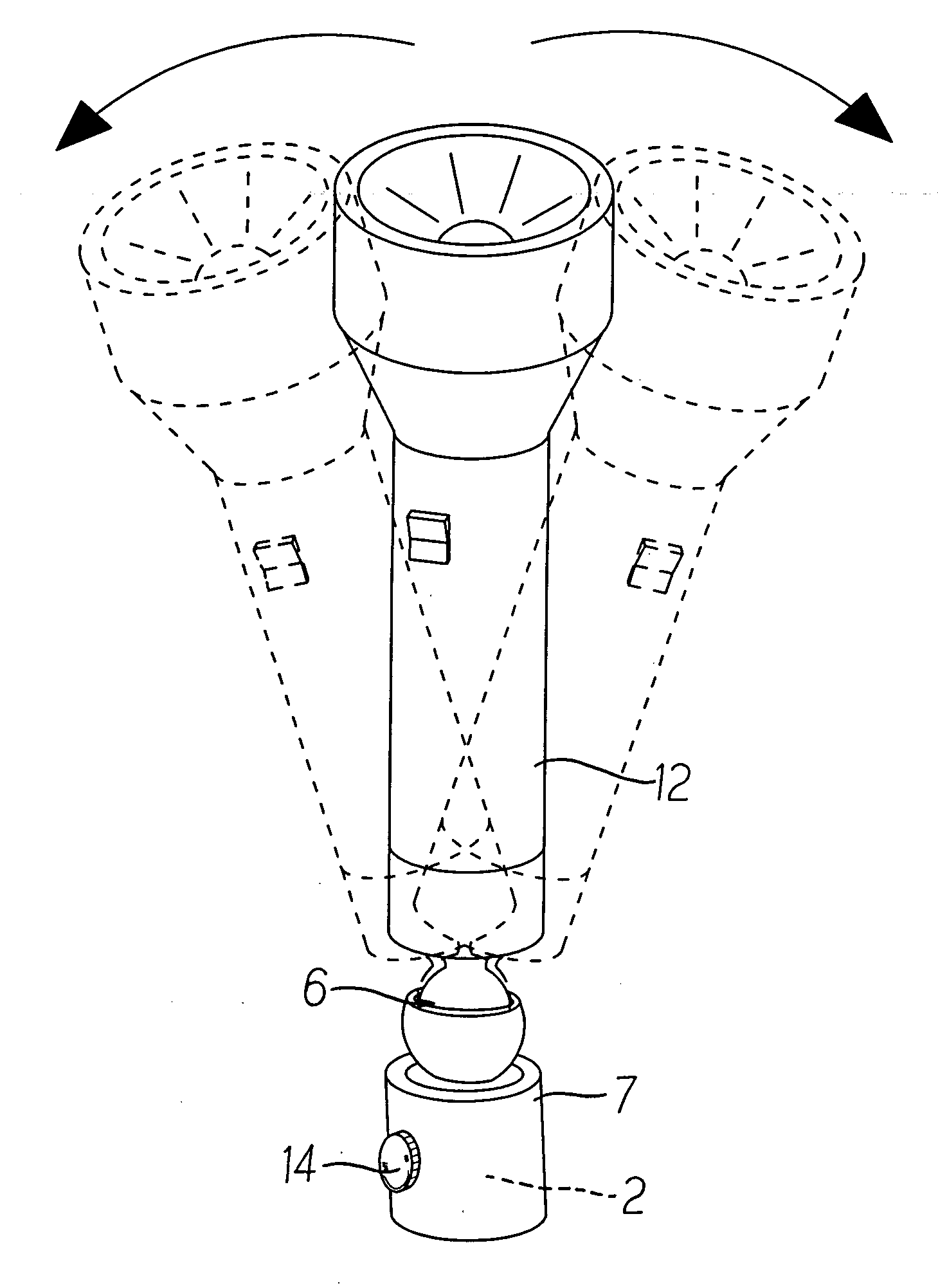
[0006] To achieve the purpose, the lighting fixture of the present invention includes a light emitting unit and a body. The body contains a cabinet to accommodate one or multiple cells to supply power to the light-emitting unit. A magnetic attraction device is disposed at where appropriately on the body and includes a magnetic member, a magnetism permeable member, a non-magnetism permeable member, and a control member. The magnetic member carries permanent magnetism. The control member controls the direction of those magnetic filed lines from the magnetic member to determine if the magnetism permeable member to carry magnetic force or not. When provided with magnetic force, the magnetism permeable member allows the lighting fixture to be attracted and held steady to a metallic surface (e.g., refrigerator, metal door panel); and the control member shifts the direction of those magnetic field lines to deprive the magnetism permeable member of magnetic attraction force for the lighting fixture to fast and easily disengage from the metal surface.

Problems solved by technology

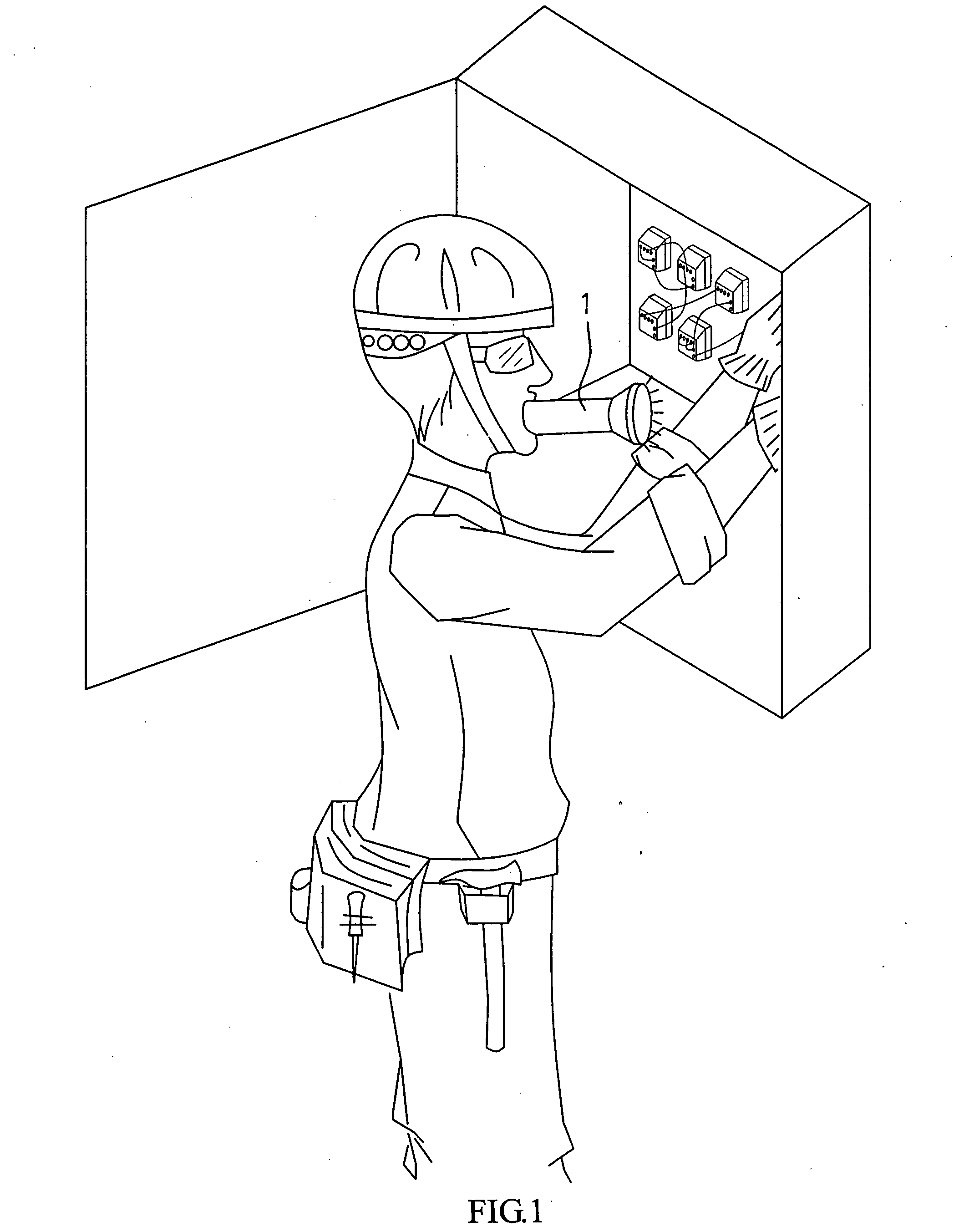
If the repair job can be done in a short while, it's OK to bite the flashlight though it presents health problem; however, the job could go longer and must be interrupted as one's mouth getting sour by holding the flashlight in his mouth.

Method used


Image

  • Lighting fixture
  • Lighting fixture
  • Lighting fixture

Examples


Embodiment Construction

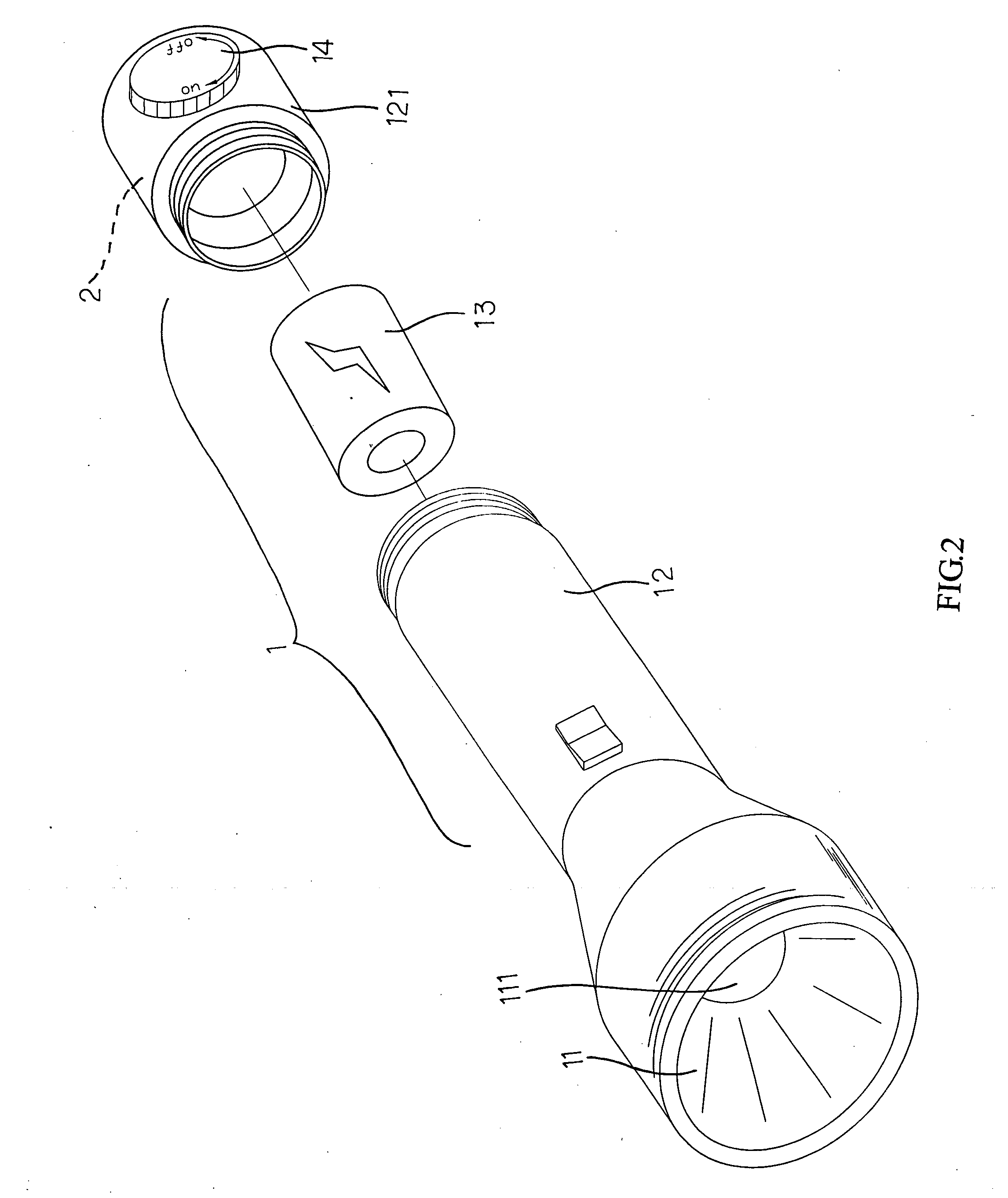
[0018] Referring to FIG. 2 for a construction of a lighting fixture 1, which in the preferred embodiment related to a flashlight includes a light emitting unit 11 and a holder 12. The light-emitting unit 11 is located at the head cap of the holder 12 of the lighting fixture to respectively provide front light emission. The holder 12 contains a cell 13 to supply power to a light-emitting device 111 disposed at the light-emitting unit 11. The tail of the holder 12 is related to a threaded bottom cap 121 and a magnetic attraction device 2 is provided to the bottom cap 121. Alternatively, the magnetic attraction device 2 is made as an integrated with the tail of the holder 12 as illustrated in FIG. 3.

[0019] Now referring to FIG. 4(A), the magnetic attraction device 2 includes magnetic member 21, magnetism permeable member 22, non-magnetism permeable member 23, and control member 24. Wherein, the non-magnetism permeable member 23 is provided between two magnetism permeable members 22 to...


PUM


Abstract

A lighting fixture includes a body and a light emitting unit; the body being provided with a magnetic attraction device comprised a magnetic member with permanent permeability and a control member to control direction of magnetic filed lines from the magnetic member for it to provide attraction force or not; the lighting fixture being attached to a metallic surface when attraction force is provided or disengaged from the metallic surface by changing the direction of those magnetic force lines in the magnetic member.

Description

BACKGROUND OF THE INVENTION [0001] (a) Field of the Invention [0002] The present invention is related to a lighting fixture, and more particularly, to one that can be attached to metallic surface (e.g., refrigerator, metal door panel) for fast and easy access. [0003] (b) Description of the Prior Art [0004] A lighting fixture (e.g., a flashlight) usually becomes handy in case of power failure or at where city power fails to reach. In case of a power failure, it takes the lighting fixture to help the repair job. As illustrated in FIG. 1 of the accompanying drawings, one has to bit a lighting fixture 1, a flashlight in this case since he has to use both hands to work. If the repair job can be done in a short while, it's OK to bite the flashlight though it presents health problem; however, the job could go longer and must be interrupted as one's mouth getting sour by holding the flashlight in his mouth. SUMMARY OF THE INVENTION [0005] The primary purpose of the present invention is to p...

Claims


Application Information

Patent Timeline
IPC IPC(8): F21V21/096F21V21/30F21L4/04
CPCF21V21/0965
Inventor WU, CHING-YIYANG, CHIEN-CHINGCHEN, CHIH-MINGHUANG, YU-FANG
Owner KENLY PRECISION INDAL
Learn More