Shrouded face seal and components thereof

a face seal and encapsulation technology, applied in the direction of engine seals, leakage prevention, machines/engines, etc., can solve the problems of incomplete wear of the nose, less favorable net pressure force for maintaining reliable, and gradual wear of the nos

a face seal and encapsulation technology, applied in the direction of engine seals, leakage prevention, machines/engines, etc., can solve the problems of incomplete wear of the nose, less favorable net pressure force for maintaining reliable, and gradual wear of the nos

US20070108704A1Active Publication Date: 2007-05-17RAYTHEON TECH CORP

Image

  • Shrouded face seal and components thereof
  • Shrouded face seal and components thereof
  • Shrouded face seal and components thereof

Examples


Embodiment Construction

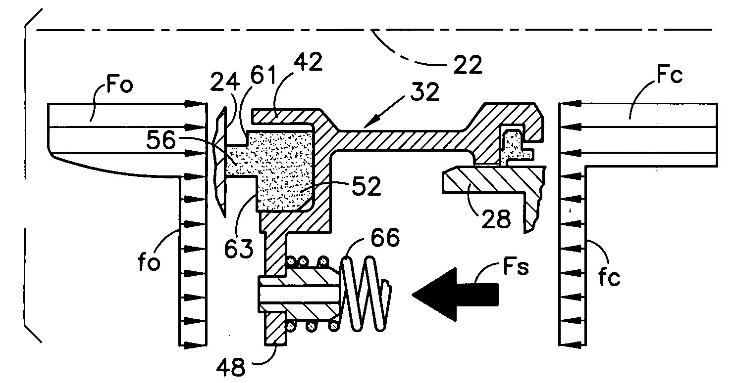
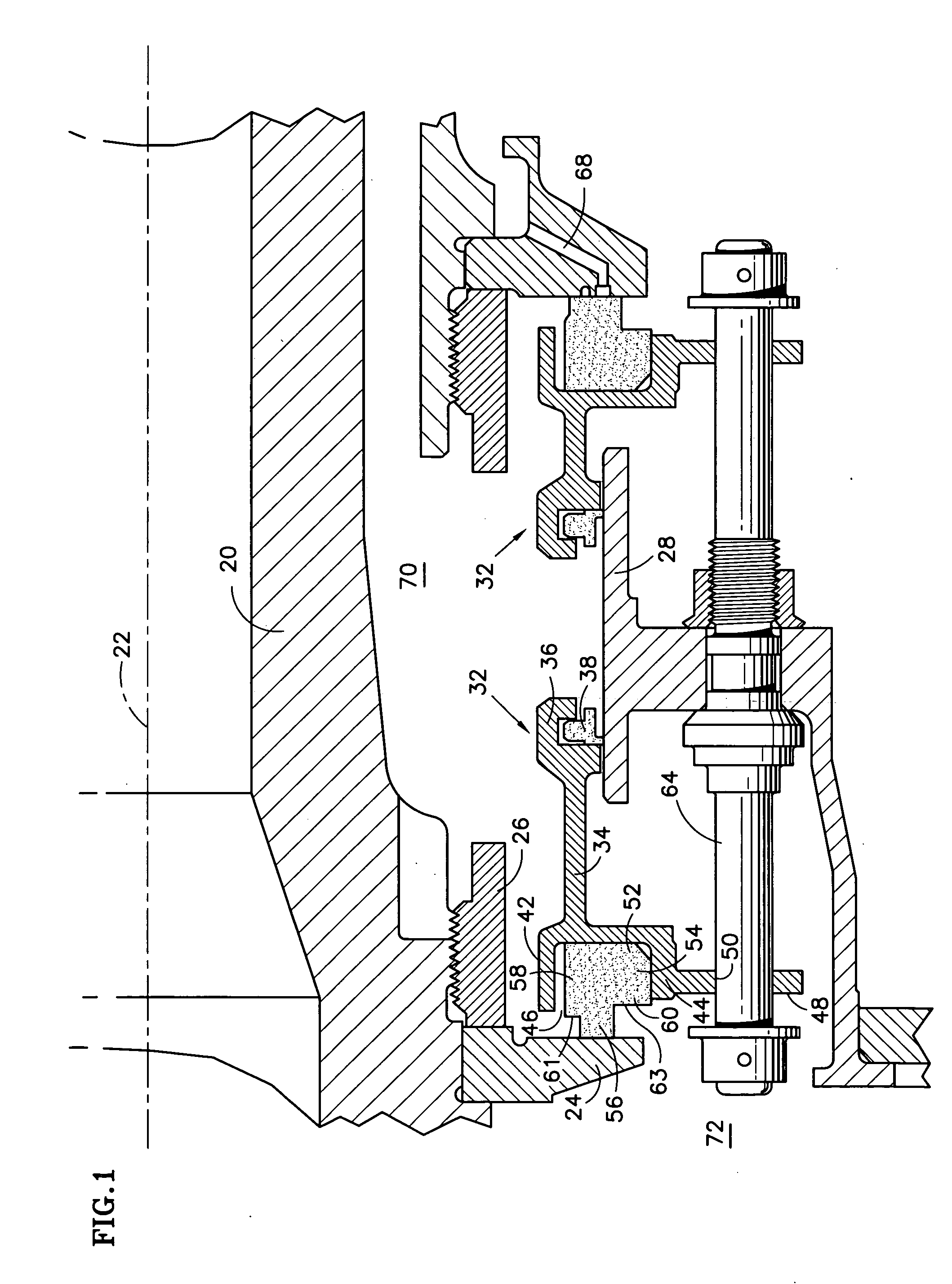
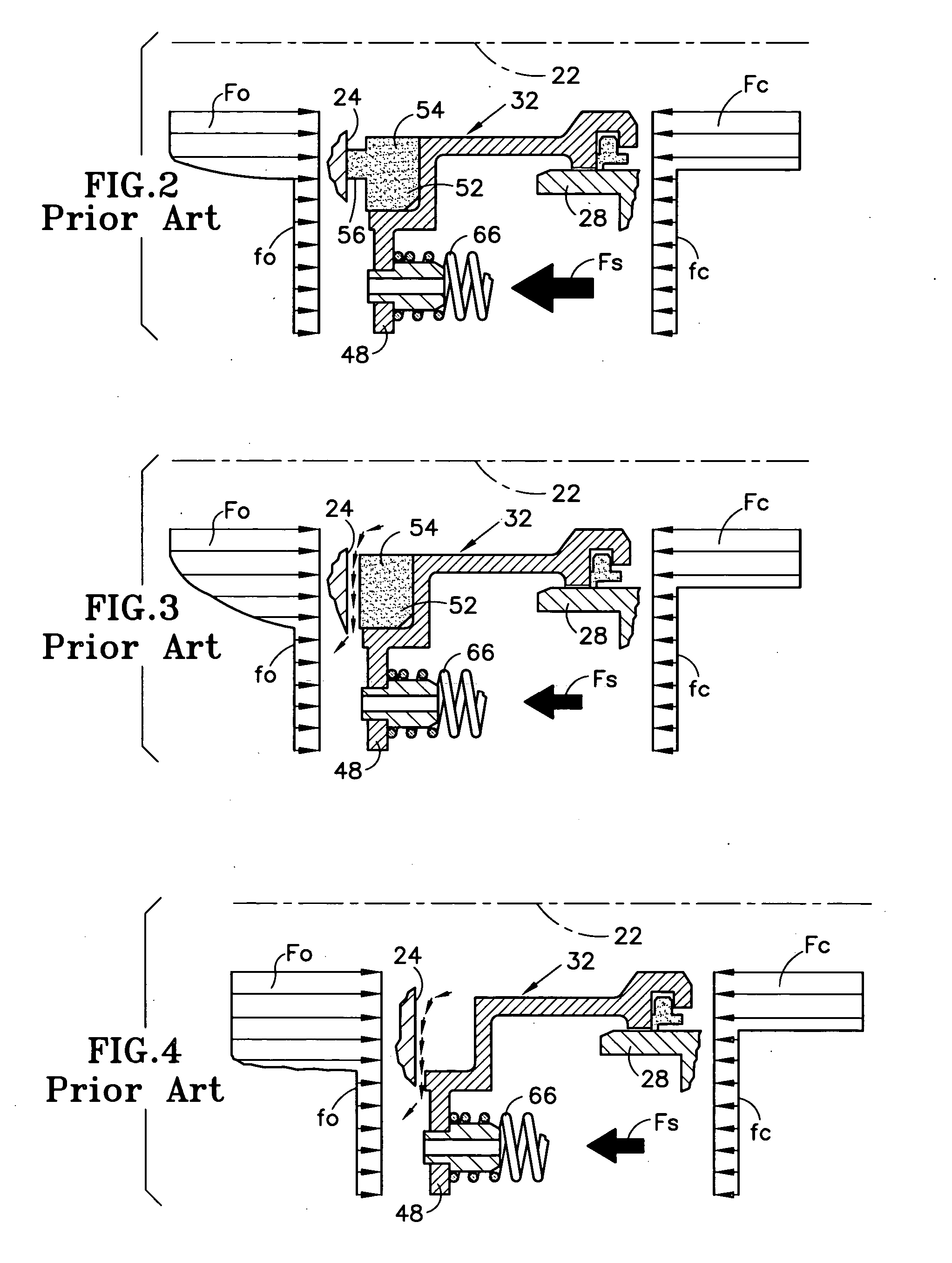
[0014] Referring to FIG. 1, a shaft 20 for a rotary machine, such as a turbine engine, is rotatable about an axis 22. A seal seat in the form of an annular ring 24 is secured against a shoulder on the shaft by a nut 26. The seal seat extends radially outwardly from the shaft and circumscribes the axis. The seal seat is one component of a face seal assembly.

[0015] The face seal assembly also includes an annular, nonrotatable seal support 28 and a pair of annular seal housings 32. Each seal housing includes a base 34 and a grooved secondary seal holder 36 at one end of the base. The secondary seal holder holds a secondary seal 38 in contact with a cylindrical bore of the seal support. The other end of the seal housing includes an axially extending shroud 42 and an axially extending support lip 44 that serves as a seal element support. The shroud 42 is radially offset from the lip 44 to define an annular space 46 for receiving a seal element. The shroud is also axially elongated relat...


PUM


Abstract

A face seal includes a seal seat 24 and a seal element 52 carried by a seal housing 32. The seal element cooperates with the seal seat to establish a seal. The housing includes a support 44 for the seal element and a shroud 42 for effecting a gradual transition between a normal condition and a deteriorated condition. The shroud 42 may have a tip 74 whose properties differ in lubricity, hardness or abradability relative to other portions of the seal housing.

Description

TECHNICAL FIELD [0001] This invention relates to face seals and particularly to a carbon face seal whose performance deteriorates in a relatively benign way in comparison to conventional seals. BACKGROUND OF THE INVENTION [0002] Carbon face seals are used in machinery, such as turbine engines, to effect a fluid seal between regions of high and low fluid pressure. For example, carbon seals are used to prevent hot, high pressure air from entering a bearing compartment operating at a lower pressure. A typical carbon seal for a turbine engine includes an annular carbon ring secured to an annular, nonrotatable, axially translatable seal housing. The seal also includes a seal seat affixed to a rotatable shaft and positioned axially adjacent to the carbon ring. The carbon ring comprises a base (or blank) and a nose projecting axially from the base. The nose is urged into contact with the seal seat by a combination of spring forces acting on the seal housing and the net resultant of axially...

Claims


Application Information

Patent Timeline
17 May 2007
Publication
US20070108704A1
IPC
F16J15/34
CPC
F01D11/003; F05D2240/55; F16J15/3468
Inventors
CRAIG, COLIN D.; DIBENEDETTO, ENZO