Directionally controllable night light

a technology of directional control and night lights, applied in the direction of lighting and heating apparatus, lighting support devices, coupling device connections, etc., can solve the problem of difficulty for a person to move around without ligh

Inactive Publication Date: 2007-05-17
AMERICAN TACK & HARDWARE
View PDF12 Cites 33 Cited by
  • Summary
  • Abstract
  • Description
  • Claims
  • Application Information

AI Technical Summary

Benefits of technology

[0010] The device of the present invention therefore comprises a housing with a rotatable bezel mounted thereon. The housing includes a rear wall with electric blades extending outwardly therefrom for engaging in an electrical wall outlet. The bezel is rotatable about a first axis. A LED array is mounted in the bezel and the array is rotatable about a second axis. The second axis is oriented on a different plane to the first axis and preferably lies at ninety degree thereto. When the bezel is rotated about the first axis

Problems solved by technology

One of the problems with previously known night lights is that they emit light in many directions which ma

Method used


Image

  • Directionally controllable night light
  • Directionally controllable night light
  • Directionally controllable night light

Examples


Embodiment Construction

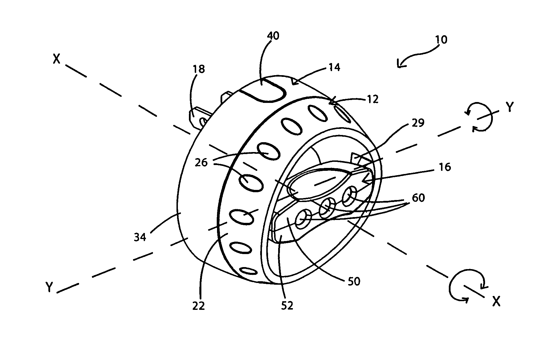
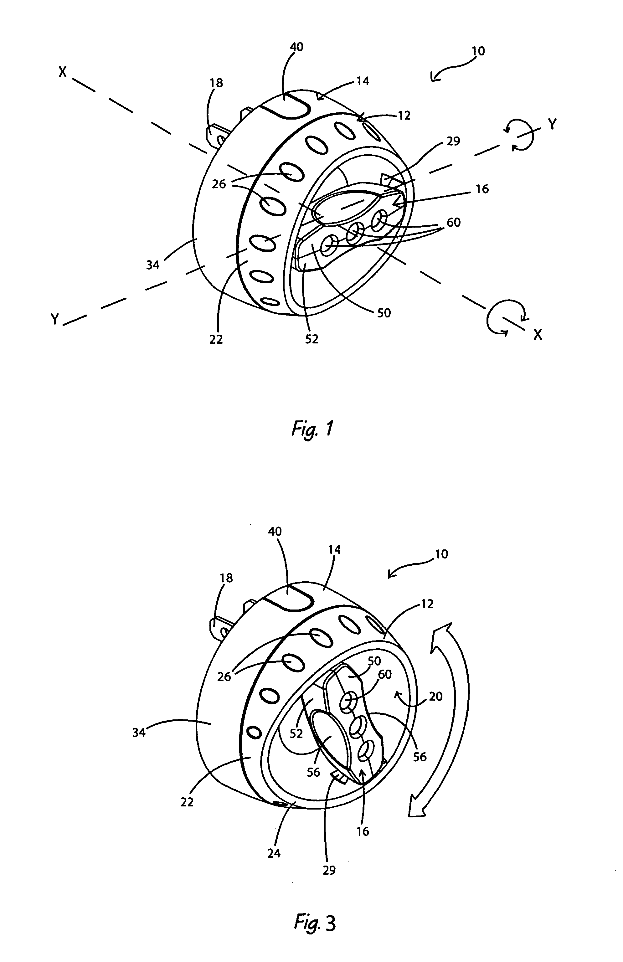
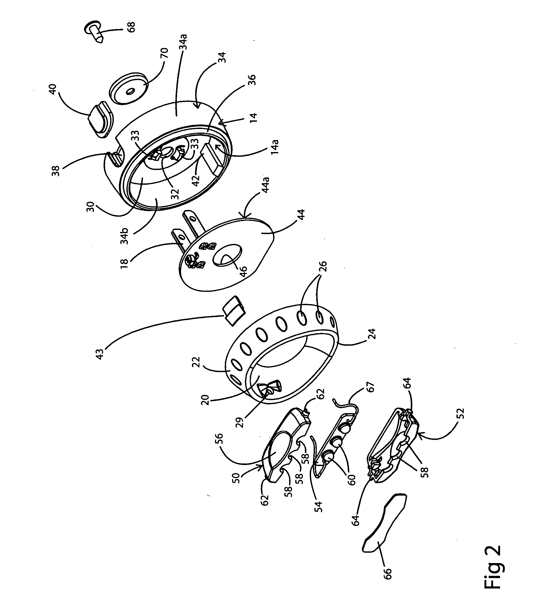
[0020] Referring to FIGS. 1-7, there is shown a night light in accordance with the present invention and generally indicated at 10. Night light 10 comprises a bezel 12 mounted on a housing 14. A narrow LED array 16 is rotatably mounted in bezel 12. Array 16 comprises a plurality of individual LEDs 60 preferably mounted on a member in substantially a straight line. Electrical blades 18 extend outwardly from a rear wall 30 (FIG. 2a) of housing 14. As will be subsequently described herein, the direction of the light emitted by the LEDs 60 can be controlled by manipulating the bezel 12 relative to the housing 14 and by manipulating the orientation of the LED array 16 within the bezel 12.

[0021] Bezel 12 is a shallow, dish-shaped body which is generally circular in appearance when viewed from the front but, cross-sectionally. The body is deeper proximate a first side 12a (FIG. 7) and shallower proximate a second side 12b. Bezel 12 comprises a wall 20 having a skirt 22 extending outwardly...


PUM


Abstract

A night light comprising a housing with a rotatable bezel mounted thereon. The housing includes a rear wall with electric blades extending outwardly therefrom for engaging in an electrical wall outlet. The bezel is rotatable about a first pivot axis. A LED array is mounted in the bezel and the array is rotatable about a second pivot axis. The second pivot axis is oriented on a different plane to the first pivot axis and preferably lies at ninety degree thereto. When the bezel is rotated about the first pivot axis, the direction of the light emitted from the LED array is changed. Because the bezel can rotate through 360°, the LED array can be rotated through 360° about the first pivot axis. The LED array can be pivoted through an arc of between 160° and 175° about the second pivot axis. The combination of being able to rotationally adjust the position of the bezel on the housing and to adjust the position of the LED array within the bezel allows the individual to control the direction of the light emitted from the night light.

Description

BACKGROUND OF THE INVENTION [0001] 1. Technical Field [0002] This invention generally relates to night lights. More particularly, the invention relates to night lights that utilize light-emitting diodes (LEDs) as the source of illumination. Specifically, the invention relates to a night light in which the direction of the emitted light can be controlled by adjusting a portion of the housing and / or by controlling the orientation of the LED array within the housing. [0003] 2. Background Information [0004] Night lights are used to provide low levels of light in passageways, bathrooms, kitchens and bedrooms so that people can negotiate their way around the house during the night without having to switch on the overhead lights or lamps and totally illuminate the room. [0005] Most night lights incorporate incandescent light bulbs which emit omnidirectional light. Other night lights incorporate one or more LEDs (light-emitting Diodes) or banks of LEDs which emit a cool light. One of the pr...

Claims


Application Information

Patent Timeline
IPC IPC(8): H01R33/00
CPCF21S8/035H01R35/04
Inventor COPELAND, STEVE A.THOMPSON, MITCHELL
Owner AMERICAN TACK & HARDWARE
Why Eureka
Try Eureka