Fixing device

Inactive Publication Date: 2007-05-17
KONICA MINOLTA BUSINESS TECH INC
View PDF4 Cites 10 Cited by
  • Summary
  • Abstract
  • Description
  • Claims
  • Application Information

AI Technical Summary

Benefits of technology

[0050] According to the fixing device in this aspect, the control section controls the load change body so that the load applied to between the fixing roller and the pressure roller during the standby time is smaller than the load during paper passing time, and therefore the fixing roller and the pressure roller are rotated during the standby time in the state that the load betwee

Problems solved by technology

However, in the conventional fixing device, when the magnetic flux generating section is operated while the fixing roller is in a stopped state during a standby time at which transportation of the recording member is not requested, there is a possibility that the fixing roller might locally generate heat and be damaged.
Moreover, during the standby time, the mere

Method used


Image

  • Fixing device
  • Fixing device
  • Fixing device

Examples


Embodiment Construction

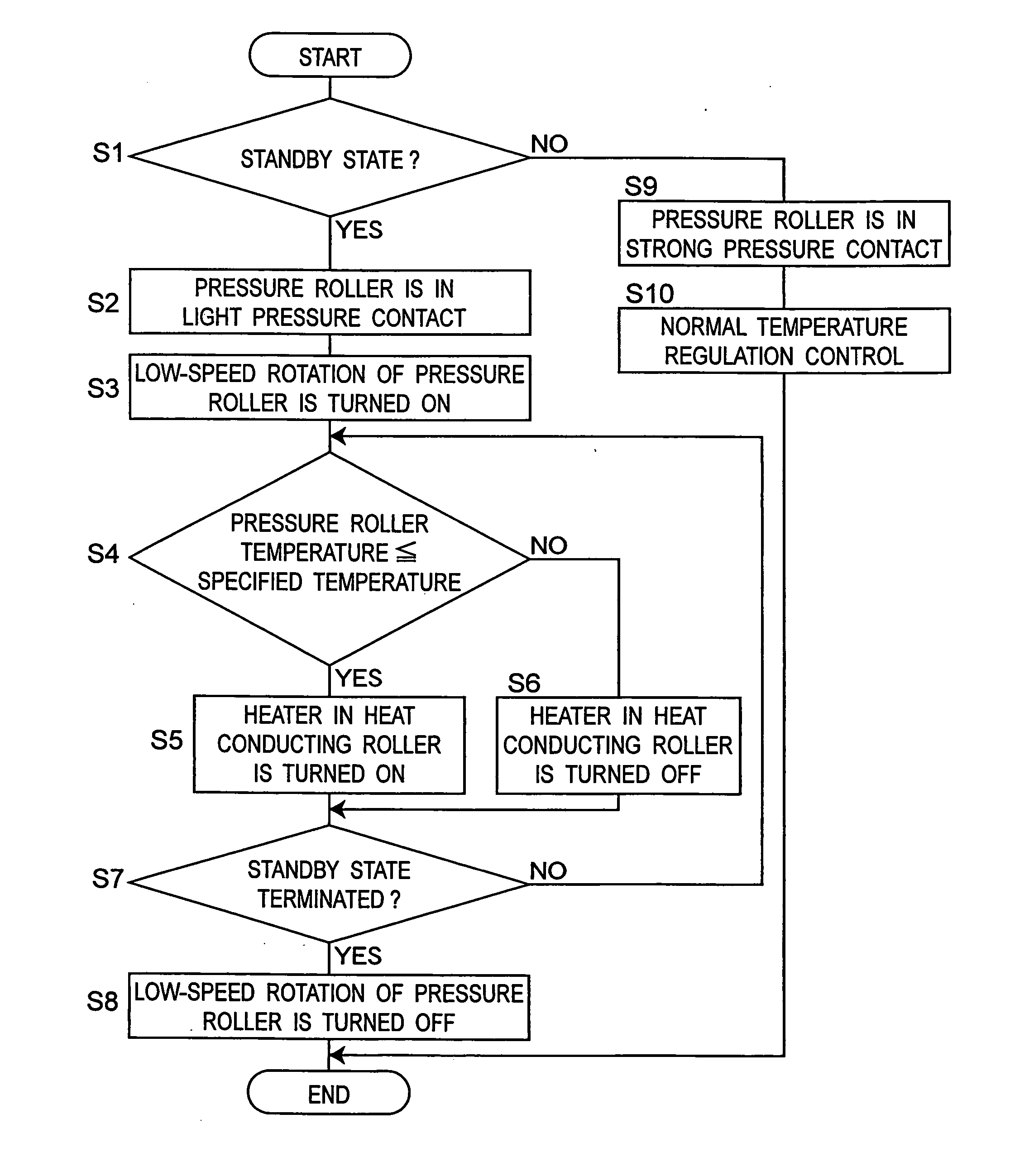
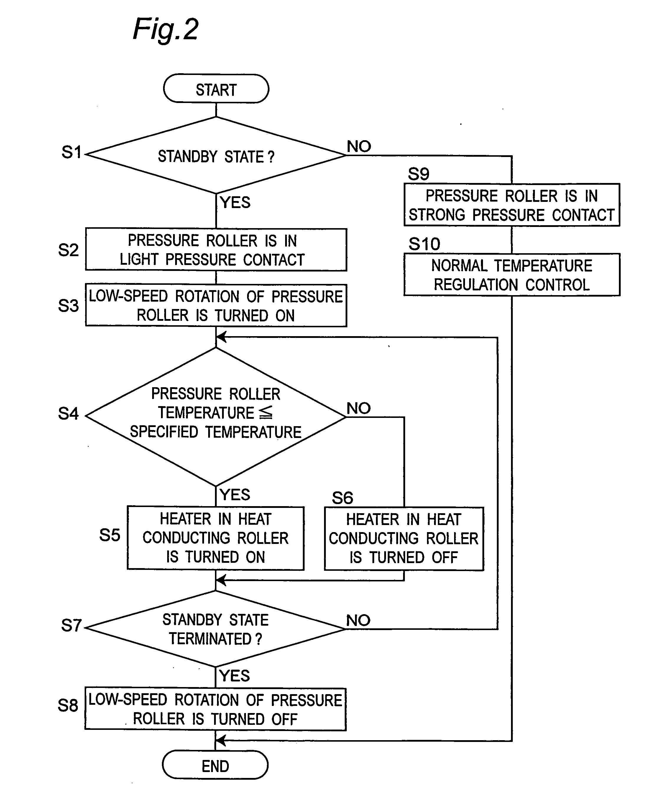
[0056] The present invention will be described hereinbelow in detail in conjunction with the embodiment with reference to the accompanying drawings.

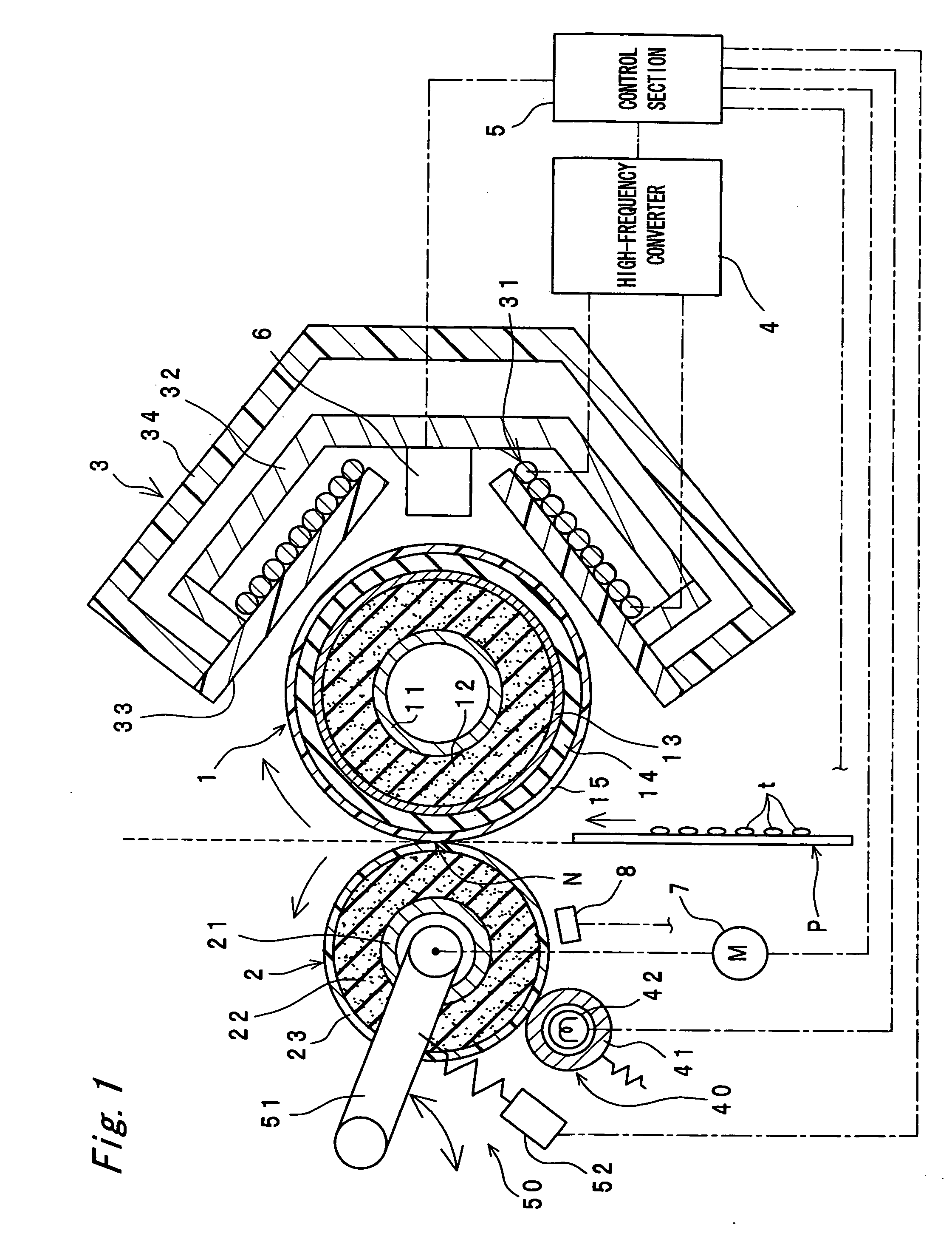
[0057]FIG. 1 is a cross sectional structure view showing a fixing device in one embodiment of the present invention. The fixing device includes a fixing roller 1 as a rotatable fixing body, a pressure roller 2 as a pressing body coming in pressure contact with the fixing roller 1, and a magnetic flux generating section 3 placed outside the fixing roller 1 for generating a magnetic flux to make the fixing roller 1 generate heat.

[0058] After the fixing roller 1 is made to generate heat by a magnetic flux from the magnetic flux generating section 3, a recording member P having an unfixed toner t attached thereto is passed through a nip section N formed from a mutual contact face between the fixing roller 1 and the pressure roller 2, and while the recording member P is transported by the nip section N, the unfixed toner t is melted and fix...


PUM


Abstract

When a fixing roller 1 generates heat by a magnetic flux generating section 3 during a standby time, a control section 5 rotates the fixing roller 1. This prevents the fixing roller 1 from locally generating heat and being damaged. Moreover, the control section 5 rotates and heats a pressure roller 2 during the standby time, which makes it possible to keep the pressure roller 2 at a specified temperature and to reduce a time taken for a fixing device to recover from the standby state.

Description

CROSS-REFERENCE TO RELATED APPLICATIONS [0001] This application is based on application No. 2005-331473 filed in Japan, the entire content of which is hereby incorporated by reference. BACKGROUND OF THE INVENTION [0002] The present invention relates to a fixing device applied to image forming apparatuses such as copiers, laser printers and facsimiles. [0003] Conventionally there is a fixing device composed of a fixing roller, a pressure roller for transporting a recording member with the fixing roller in the state of being in contact with the fixing roller, and a magnetic flux generating section placed outside the fixing roller for generating a magnetic flux to make the fixing roller generate heat (see JP 2000-214713 A). [0004] However, in the conventional fixing device, when the magnetic flux generating section is operated while the fixing roller is in a stopped state during a standby time at which transportation of the recording member is not requested, there is a possibility that...

Claims


Application Information

Patent Timeline
IPC IPC(8): G03G15/20
CPCG03G15/205
Inventor OHNO, YASUHIROMASUDA, TOMOHIKOKAMODA, YUJIIWAHASHI, HARUO
Owner KONICA MINOLTA BUSINESS TECH INC
Why Eureka
Try Eureka