Latch system for door

Inactive Publication Date: 2016-05-26
WOOBO TECH
View PDF1 Cites 3 Cited by
  • Summary
  • Abstract
  • Description
  • Claims
  • Application Information

AI Technical Summary

Benefits of technology

[0010]The latch system of the door of the present invention, as described above, has the following effects.
[0011]The locking member which locks the latch includes the sliding member which is slidably installed at the housing, and thus the number of components can be remarkably reduced.
[0012]Since the locking member is slidably installed at the housing, the locking member can be formed in the thick bar shape, and thus the durability of the system can be further enhanced.
[0013]Since the lever connecting part which is connected with the door lever to slide the sliding member is connected to the sliding member, and the sliding member has the moving space in which the lever connecting part is movable in the pulling direction when the door-out-lever connecting part is pulled after the safety device is locked, the wire can be prevented from being bent, and position correction can be performed.
[0014]The latch is disposed at one side of the sliding member, and the first safety device is rotata

Problems solved by technology

Due to the many components, there are some problems in that manufactur

Method used


Image

  • Latch system for door
  • Latch system for door
  • Latch system for door

Examples


Example

First Embodiment

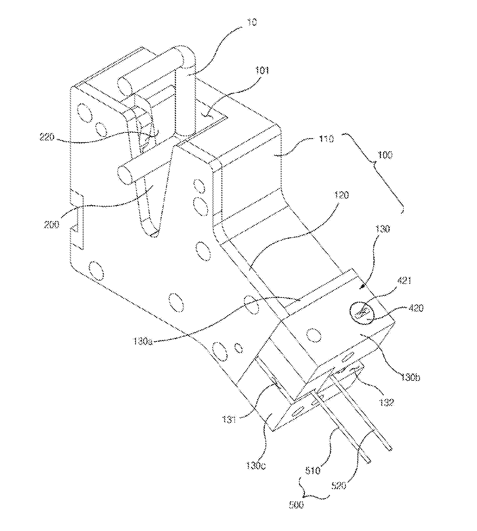
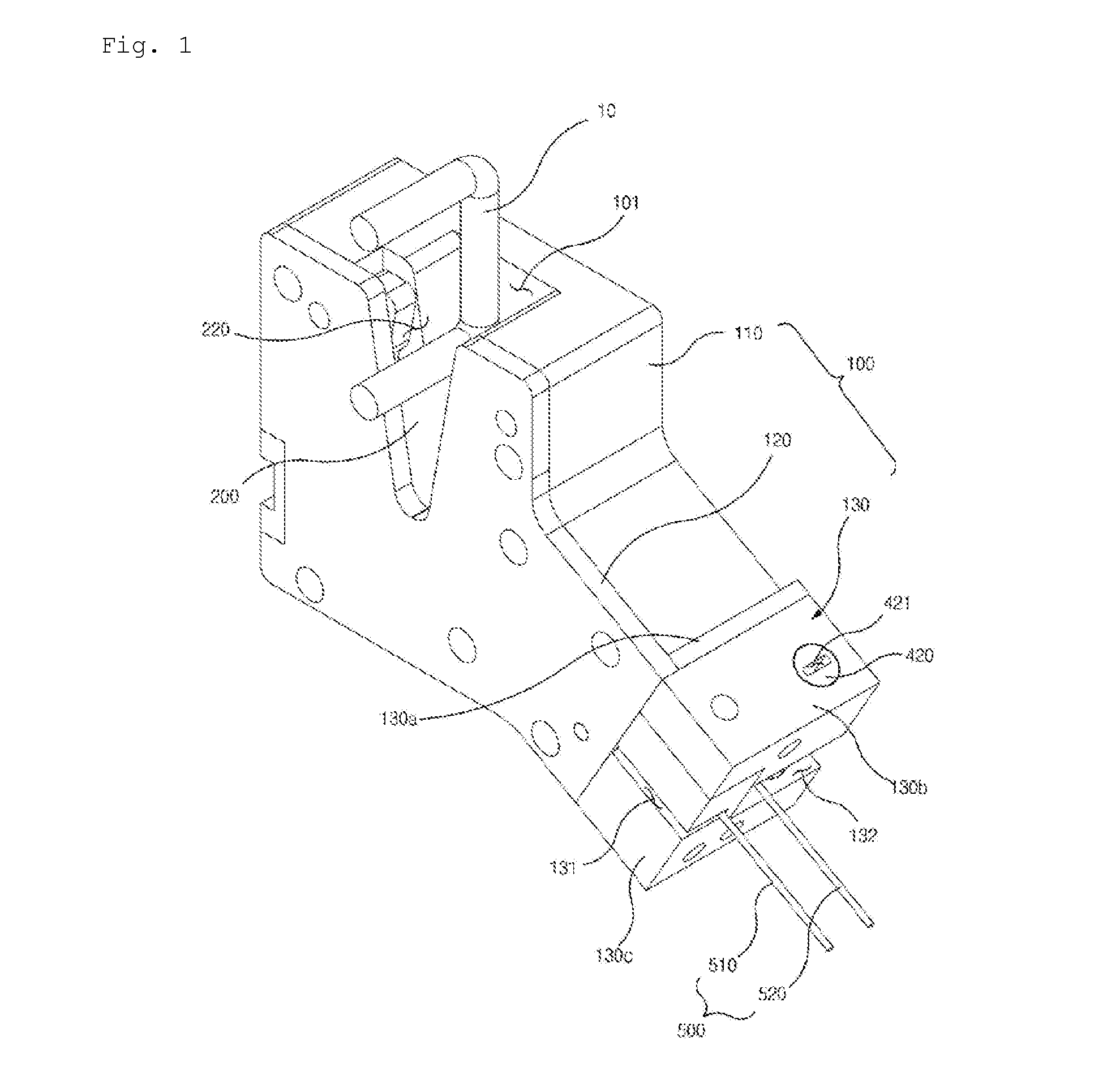
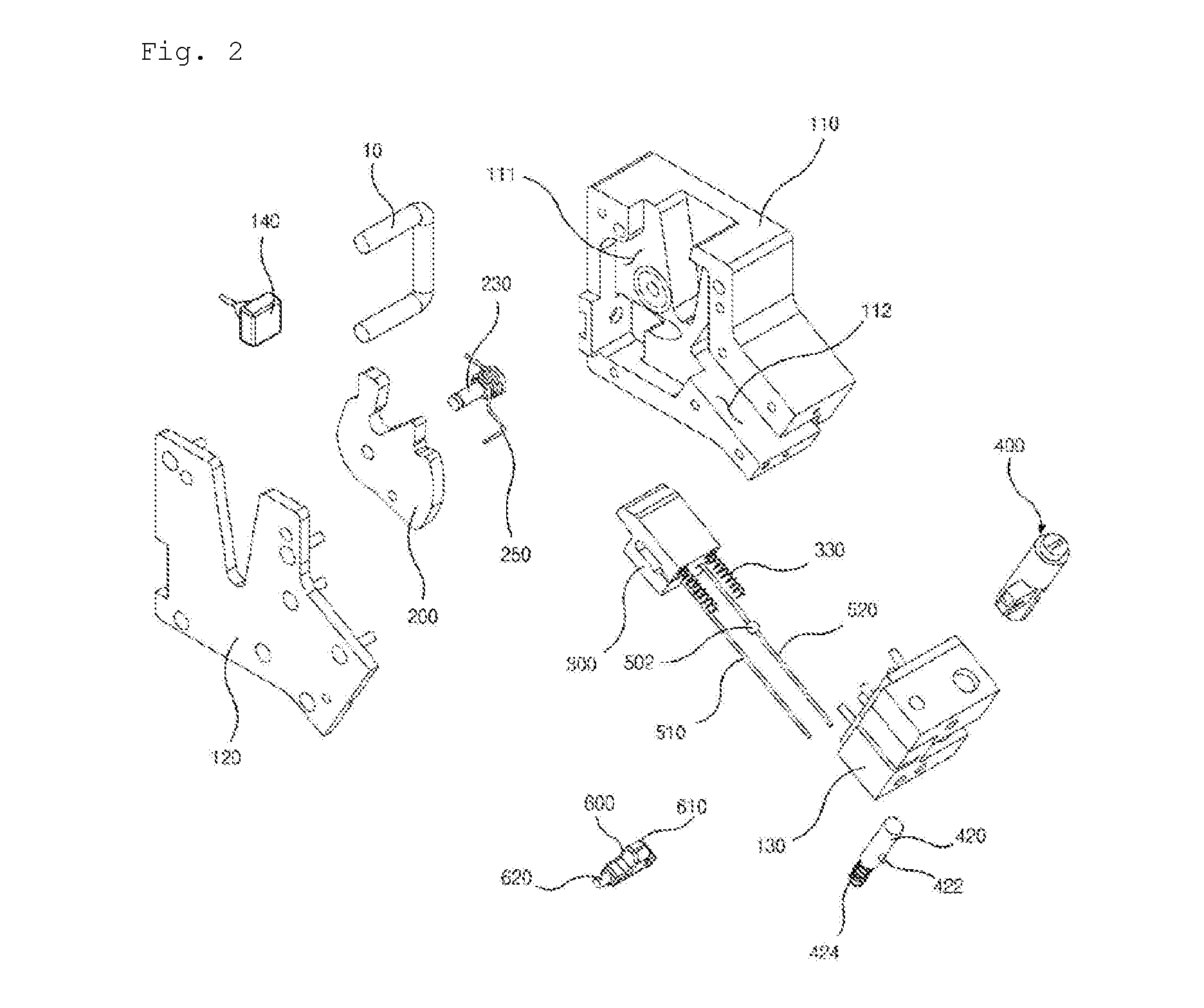
[0055]As illustrated in FIGS. 1 to 8, a latch system for a door in accordance with a first embodiment of the present invention includes a housing 100, a latch 200 which is rotatably installed at the housing 100, and a locking member which is installed at the housing 100 to lock the latch 200. The locking member includes a sliding member 300 which is slidably installed at the housing 100, the latch 200 is rotatably installed, and the sliding member 300 is installed to be linearly movable.

[0056]The housing 100 includes a first housing 110, a second housing 120 which is disposed in front of the first housing 110, and a third housing 130 which is disposed at side parts of the first and second housings 110 and 120.

[0057]A link insertion groove 101 in which a link 10 connected to a door (not shown) is inserted is formed at upper and front portions of the housing 100.

[0058]The first housing 110 is formed in a block shape, and a latch seating groove 111 (which will be descri...

Example

Second Embodiment

[0143]As illustrated in FIGS. 9 to 12, a latch system for a door in accordance with a second embodiment of the present invention further includes a latch driving part 240′ which rotates a latch 200″ to a locking position.

[0144]The illustration and description of the elements of the embodiment which are similar to or the same as those in the first embodiment will be omitted.

[0145]A motor or the like is used as the latch driving part 240, and the latch driving part 240 is installed at a rear side of a first housing 110″ by a driving part bracket 243.

[0146]A stopping part 242 is formed at a shaft 241 of the latch driving part 240 to protrude forward.

[0147]The stopping part 242 is disposed to be radially spaced from the shaft 241.

[0148]A reduction gear (not shown) is installed at the shaft 241 of the latch driving part 240.

[0149]A stopping part guide groove 116 is formed at a left side of the first housing 110″ to be in communication with the spring through-hole 113.

[01...

Example

Third Embodiment

[0183]As illustrated in FIGS. 13 to 17, in a latch system for a door in accordance with a third embodiment of the present invention, the locking member includes a rotating member 340 which is rotatably installed at a housing 100′ and a sliding member 300′.

[0184]The illustration and description of the elements of the embodiment which are similar to or the same as those in the first embodiment will be omitted.

[0185]A groove-shaped spring moving part 113′ in which the first return spring 250 is moved is formed at a front surface of a first housing 110′ to be in communication with a latch seating groove 111′. The spring moving part 113′ is disposed in the latch seating groove 111′.

[0186]As illustrated in FIG. 15, a rotating member seating groove 115 is formed at the front surface of the first housing 110′ to be disposed at a right upper portion of the latch seating groove 111′. The rotating member seating groove 115 is in communication with the latch seating groove 111′....


PUM


Abstract

This invention relates to a latch system for a door, and more particularly, to a latch system for a door, in which a locking member configured to lock a latch includes a sliding member slidably installed at a housing.

Description

TECHNICAL FIELD[0001]This invention relates to a latch system for a door, and more particularly, to a latch system for a door, in which a locking member configured to lock a latch includes a sliding member slidably installed at a housing.BACKGROUND ART[0002]In a door latch system, as described in Korean Patent No. 10-1091658, a latch and a link which locks the latch are installed at a case.[0003]However, such a conventional door latch system includes many links to perform various functions. Due to the many components, there are some problems in that manufacturing cost is increased, and an assembling operation becomes complicated.SUMMARY OF INVENTIONTechnical Problem[0004]The present invention is directed to a latch system for a door, which is capable of remarkably reducing the number of components.Solution to Problem[0005]According to an aspect of the present invention, there is provided a latch system for a door including a housing, a latch rotatably installed at the housing, and a...

Claims


Application Information

Patent Timeline
IPC IPC(8): E05B15/00
CPCE05B15/0046E05B77/54E05B79/20E05B81/20E05B81/25E05B81/30E05B85/26E05C3/24E05B17/0029B60J5/00E05B77/00E05B77/26
Inventor JEONG, HAE II
Owner WOOBO TECH
Why Eureka
Try Eureka