Pump apparatus for ink jet printer

Inactive Publication Date: 2006-03-28
SAMSUNG ELECTRONICS CO LTD
View PDF6 Cites 6 Cited by
  • Summary
  • Abstract
  • Description
  • Claims
  • Application Information

AI Technical Summary

Benefits of technology

[0025]Also, according to the pump apparatus of the present invention, the collision noise does not occur during the operation, and the tube is prevented from

Problems solved by technology

Accordingly, when the pump apparatus is used for a long time, the properties of the rubber-made damper plate 16 such as elasticity and surface friction coefficient are deteriorated and thus reliability of the

Method used


Image

  • Pump apparatus for ink jet printer
  • Pump apparatus for ink jet printer
  • Pump apparatus for ink jet printer

Examples


Example

[0039]Reference will now be made in detail to embodiments of the present invention, examples of which are illustrated in the accompanying drawings, wherein like reference numerals refer to the like elements throughout. The embodiments are described below in order to explain the present invention by referring to the figures.

[0040]Hereinafter, a pump apparatus for an inkjet printer according to an embodiment of the present invention will be described with reference to the accompanying drawings.

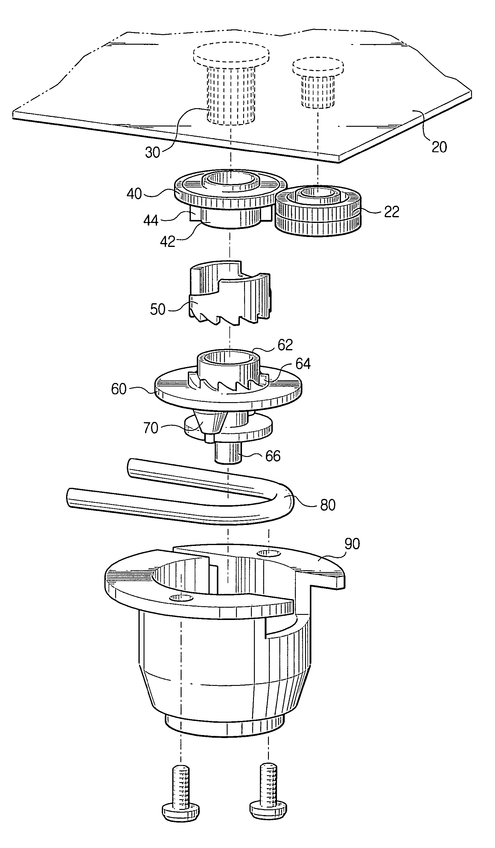
[0041]Referring concurrently to FIGS. 3 to 6, the pump apparatus for the inkjet printer according to a first embodiment of the present invention includes a fixing shaft 30, a driving gear 40, a ratchet wheel 50, a rotor 60, a tube 80, and a housing 90.

[0042]The fixing shaft 30 is fixed to a frame 20 of the inkjet printer in which the pump apparatus is disposed, and guides the rotation of the driving gear 40 and the rotor 60.

[0043]FIG. 5 shows that the driving gear 40 is rotatably disposed on the...


PUM


Abstract

A pump for an inkjet printer applying a negative pressure to an inkjet head nozzle, includes: a tube connected to the inkjet head nozzle and being U-shaped; a plurality of rollers which contact an inner arch of the tube and having a tapered shape; and a rotor to which the plurality of rollers are rotatably mounted. When the rotor rotates in a direction, at least one of the plurality of rollers rotate and squeeze the tube. When the rotor stops rotating, the plurality of rollers return to a state in which the plurality of rollers do not squeeze the tube due to a recovering force of the tube. The squeezing of the tube generates the negative pressure in the inkjet head nozzle.

Description

CROSS-REFERENCE TO RELATED APPLICATIONS[0001]This application claims the benefit of Korean Application No. 2002-83522, filed Dec. 24, 2002, in the Korean Intellectual Property Office, the disclosure of which is incorporated herein by reference.BACKGROUND OF THE INVENTION[0002]1. Field of the Invention[0003]The present invention relates to a pump for an inkjet printer, and more particularly, to a pump for an inkjet printer which squeeze a tube to generate a suction force, thereby sucking ink from an inkjet head nozzle.[0004]2. Description of the Related Art[0005]An inkjet printer using a permanent head, which can be permanently used and refilled (replenished) with ink, and a semi-permanent head, generally includes a pump. The pump for the inkjet printer performs a sucking operation in order to remove air that may enter during the replenishing of the ink and to open a head nozzle when the head nozzle is blocked by dried ink.[0006]Pumps used in inkjet printers are generally divided int...

Claims


Application Information

Patent Timeline
IPC IPC(8): B41J2/165B41J2/175
CPCB41J2/17596B41J2/175
Inventor YOUN, KARP-SIK
Owner SAMSUNG ELECTRONICS CO LTD
Why Eureka
Try Eureka