Dispersion discrimination and compensation system and optical switch for use therewith
Inactive Publication Date: 2006-05-02
RPX CLEARINGHOUSE
View PDF8 Cites 9 Cited by
Summary
Abstract
Description
Claims
Application Information
AI Technical Summary
This helps you quickly interpret patents by identifying the three key elements:
Problems solved by technology
Method used
Benefits of technology
[0014]In some embodiments of the invention, the number of components needed for the dispersion compensating switch is reduced by using a scanning front end already
Problems solved by technology
In an optical telecommunication system, the frequency dependence of the delay may be problematic.
Therefore, the upper and lower side-bands will be out of phase and can interfere destructively to reduce the amplitude of the side-band components at the receiver.
Those skilled in the art will appreciate that such modifications to a signal may lead to information loss if they are not corrected.
In a conventional optical system, signals are propagated over multiple spans before a substantial, expensive and approximate banded dispersion compensator is deployed.
One disadvantage of this approach is the reduction in the width of the “low dispersion” frequency window, which comprises those frequencies that are close
Method used
Image
Click on the blue label to locate the original text in one second.
Reading with bidirectional positioning of images and text.
Examples
Example
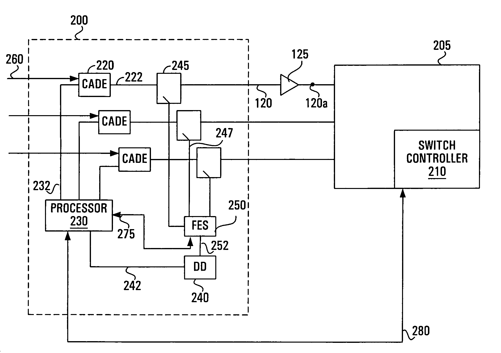
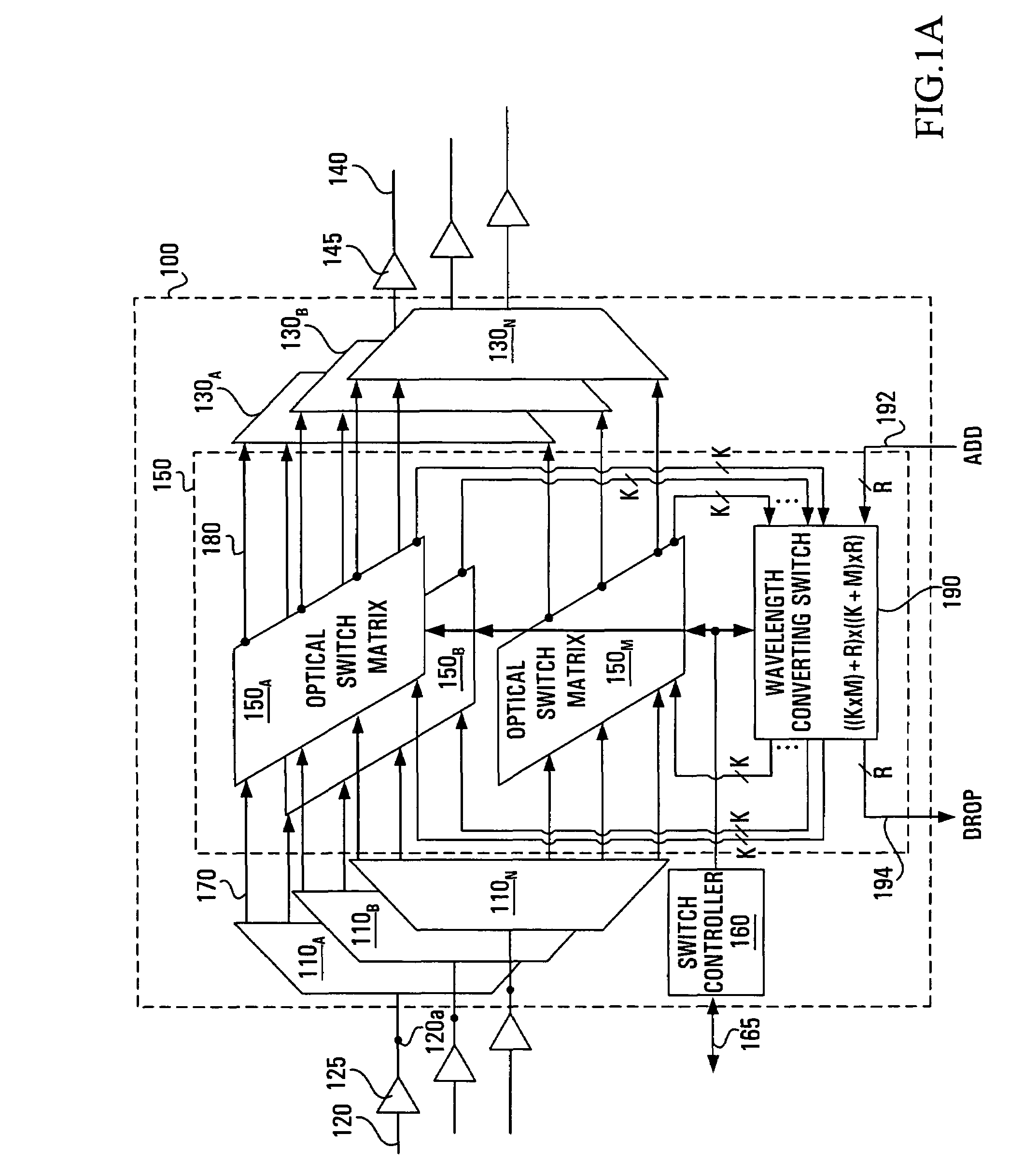
[0039]In a first embodiment, the present invention provides a Dispersion Discrimination and Compensation (DDC) subsystem that can be added to a photonic switch. By way of a non-limiting example, FIG. 1 shows a conventional switch that can be used in conjunction with the present invention. The conventional switch depicted in FIG. 1 will be briefly described. It is more fully described in above-referenced co-pending U.S. patent application Ser. No. 09 / 511,065.
[0040]The photonic switch 100 typically comprises N individual M-output wavelength division demultiplexing (WDD) devices 110A–110N, where each WDD device is associated with a respective one of N input optical fibers 120 connected to a respective set of N amplifiers 125. The photonic switch 100 also comprises N individual M-input wavelength division multiplexing (WDM) devices 130A–130N, one WDM device for each of N output optical fibers 140 connected to a respective set of N amplifiers 145.
[0041]The photonic switch 100 also compri...
PUM
Abstract
A variable dispersion compensation to a signal for compensating dispersion present in an optical signal. The invention can be embodied in a dispersion discrimination and compensation system comprising a feedback loop for regulating an amount of dispersion compensation applied by a controlable anti-dispersive element (CADE) to an incoming optical signal. To that effect, the feedback loop comprises a dispersion discriminator for accepting a portion of a signal outgoing form the CADE and to provide a measure of a dispersion characteristic to a processor which controls the amount of dispersion compensation applied by the CADE. The dispersion discrimination and compensation system can be stand-alone or integrated into an optical switch. Furthermore, dispersion compensation can be provided to multichannel optical signals or to partially or totally demultiplexed optical signals.
Description
CROSS-REFERENCES TO RELATED APPLICATIONS[0001]The present application is related in subject matter to co-pending U.S. patent applications Ser. No. 09 / 859,544 to Graves et al., entitled “Optical Switch with Connection Verification”, filed on May 18, 2001; Ser. No. 09 / 742,232 to Van Schyndel, entitled “Gain Determination for Correlation Processes”, filed on Dec. 22, 2000; Ser. No. 09 / 511,065 to Graves et al., entitled “Switch for Optical Signals”, filed on Feb. 23, 2000; Ser. No.60 / 207,292 to Graves et al., entitled “Optical Switch with Connection Verification”, filed on May 30, 2000; Ser. No. 09 / 842,236 to Graves, entitled “Chromatic Dispersion Discriminator”, filed on Apr. 26, 2001; and Ser. No. 09 / 580,495 to Graves et al., entitled “Optical Switch with Power Equalization”, filed on May 30, 2000, all assigned to the assignee of the present invention and hereby incorporated by reference herein in their entirety.FIELD OF THE INVENTION[0002]The present invention relates generally to sy...
Claims
Application Information
Patent Timeline
Application Date:The date an application was filed.
Publication Date:The date a patent or application was officially published.
First Publication Date:The earliest publication date of a patent with the same application number.
Issue Date:Publication date of the patent grant document.
PCT Entry Date:The Entry date of PCT National Phase.
Estimated Expiry Date:The statutory expiry date of a patent right according to the Patent Law, and it is the longest term of protection that the patent right can achieve without the termination of the patent right due to other reasons(Term extension factor has been taken into account ).
Invalid Date:Actual expiry date is based on effective date or publication date of legal transaction data of invalid patent.