Canopy Of Working Vehicle

Inactive Publication Date: 2008-01-10
YANMAR POWER TECHNOLOGY CO LTD
View PDF4 Cites 8 Cited by
  • Summary
  • Abstract
  • Description
  • Claims
  • Application Information

AI Technical Summary

Benefits of technology

[0018] In the present invention, the frame forming the back part of the canopy is formed by connecting the upper ends of the support columns to a pipe for mounting a roof of the canopy, and the front ends of the pipes for mounting the roof is connected by way of a three directional pipe joint with respect to the support column of the front part of the canopy and a plurality of pipes forming a roof mounting part to form a canopy frame, and thus the number of components forming the frame of the canopy is reduced, assembly is facilitated, and the manufacturing cost is reduced.
[0019] In the present invention, the three directional pipe joint is formed by casting, and thus the number of components forming the frame of the canopy is reduced, assembly is facilitated, and the manufacturing cost is reduced.
[0020] In the present invention, a roof of the canopy is arranged on the three directional pipe joint, and a roof attachment seat of the canopy is integrally formed with the three directional pipe joint, and thus the number of components forming the frame of the canopy is reduced, and the aesthetic outer appearance of the canopy is improved.
[0021] In the present invention, the frame forming the back part of the canopy is formed by connecting th

Problems solved by technology

However, in the tractor disclosed in patent document 1, the space between the operator's seat and the safety frame is narrow, and thus is troublesome when the

Method used


Image

  • Canopy Of Working Vehicle
  • Canopy Of Working Vehicle
  • Canopy Of Working Vehicle

Examples


Embodiment Construction

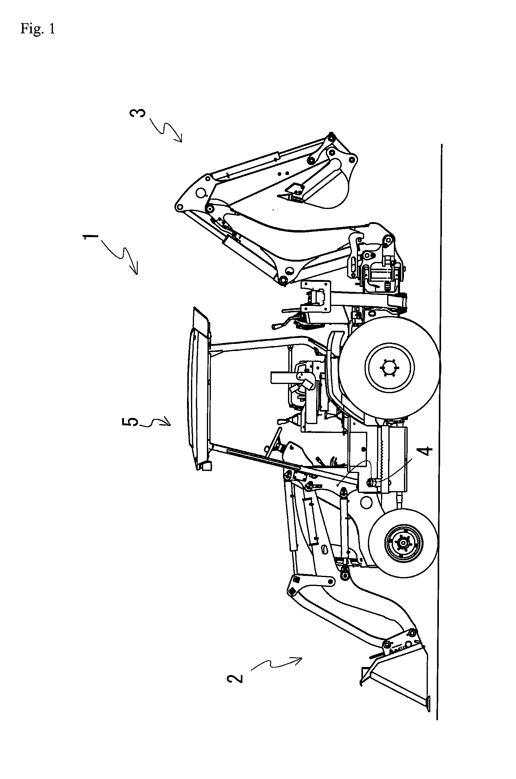
[0036] An example of the present invention will now be described using the figures. FIG. 1 is a side view of the entire backhoe loader including a canopy. The work vehicle 1 is a backhoe loader, where the loader 2 serving as a loading device and a drilling device 3 are attached to the work vehicle 1. A bracket 4 is arranged on both left and right sides of the bonnet of the work vehicle 1, which bracket 4 is fixed to the vehicle body frame of the work vehicle 1. A canopy 5 is arranged on the vehicle body frame, and the operator operates the work vehicle in the canopy 5.

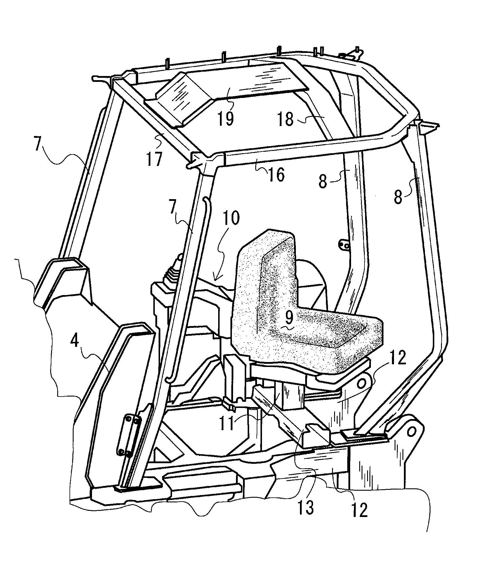
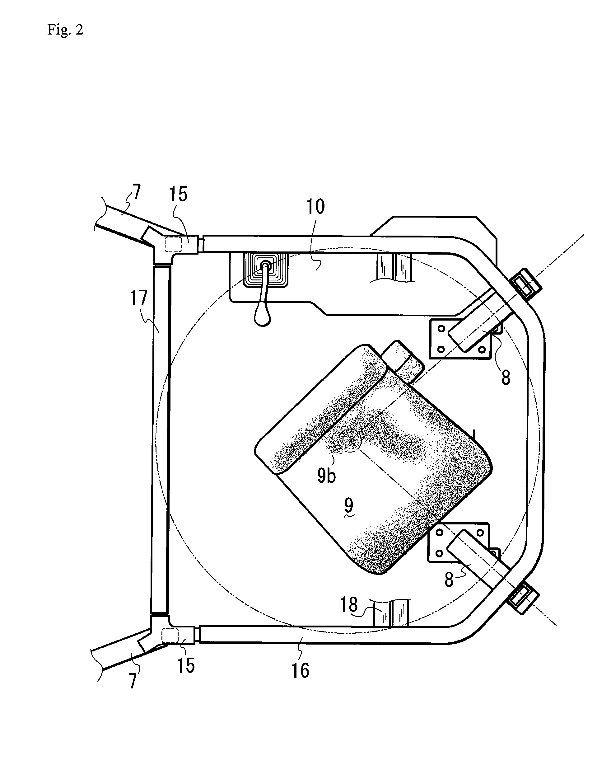
[0037] The structure of the frame configuring the canopy will now be described using FIGS. 2 to 4. FIG. 2 is a plan view showing the frame structure of the canopy, FIG. 3 is a side view of the same, FIG. 4 is a perspective view of the same, and FIG. 5 is a plan view showing the structure of the top frame. The canopy 5 is configured by front frames 7, 7, rear frames 8, 8, a top frame 16, and a front top frame 17. The f...


PUM


Abstract

A canopy of a working vehicle having, therein, a forwardly and reversely rotatable seat and enabling an increase in the rigidity of a canopy frame with a low cost and simple structure, wherein frames forming the back part of the canopy are disposed radially from the rotating axis of the seat in the canopy in plan view and bent toward the inside of the canopy, and the heights of the bent points of the frames are generally aligned with the height of the seat surface of the seat and disposed in the canopy.

Description

BACKGROUND OF THE INVENTION [0001] 1. Field of the Invention [0002] The present invention relates to a structure of a canopy arranged in a working vehicle, more specifically, to a frame structure of the canopy having, therein, a rotatable seat. [0003] 2. Background Art [0004] A work vehicle called Backhoe Loader is conventionally known in which a front loader is attached to the front part of the tractor vehicle body, and a backhoe is attached to the back part (see e.g., patent document 1). In the backhoe loader, the operator's seat is disposed in a freely forward and backward reverse rotatable manner on the tractor vehicle body by way of a reverse rotation support device, where the operator's seat faces the front when the tractor is traveling or when using the front loader and the operator's seat faces the back when using the backhoe by the reverse rotation support device. The reverse rotation device of the operator's seat is configured by parallel links and a turntable. ROPS (Roll ...

Claims


Application Information

Patent Timeline
IPC IPC(8): B62D25/08
CPCB60R21/11B62D33/0625B60R2021/0081B62D27/023
Inventor AYABE, HIROAKI
Owner YANMAR POWER TECHNOLOGY CO LTD
Why Eureka
Try Eureka