Brake disk

Inactive Publication Date: 2011-11-03
ROBERT BOSCH GMBH
View PDF8 Cites 6 Cited by
  • Summary
  • Abstract
  • Description
  • Claims
  • Application Information

AI Technical Summary

Benefits of technology

[0006]By contrast, the brake disk according to the present invention has the advantage that the number of components of the brake disk is reduced. In this connection, the various operations are also reduced. Supporting ring, connecting links and friction ring are able to be produced in one operation. During the casting process of the disk chamber, that is made of aluminum, the friction ring may be cast integrally with it. This reduces the costs of the various operations, and provides a possibility of producing a so-called “low-cost brake disk”. Because of the special positioning of the bevels of the studs of the supporting ring, in response to the shrinking of the disk chamber made of aluminum and cast integrally,

Problems solved by technology

In the case of larger braking torques, there is a danger that, based on the free length of the connecting links, that is, based on the distance between supporting structure and friction ring, the connecting links, might bend and, in the extreme case, detach from their seat.
These known brake disks are characteri

Method used


Image

  • Brake disk
  • Brake disk
  • Brake disk

Examples


Example

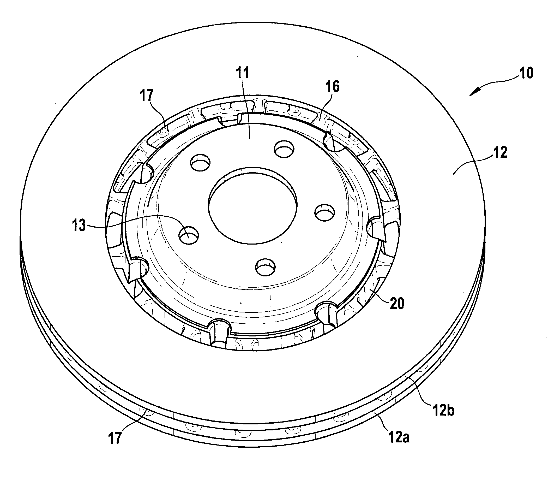
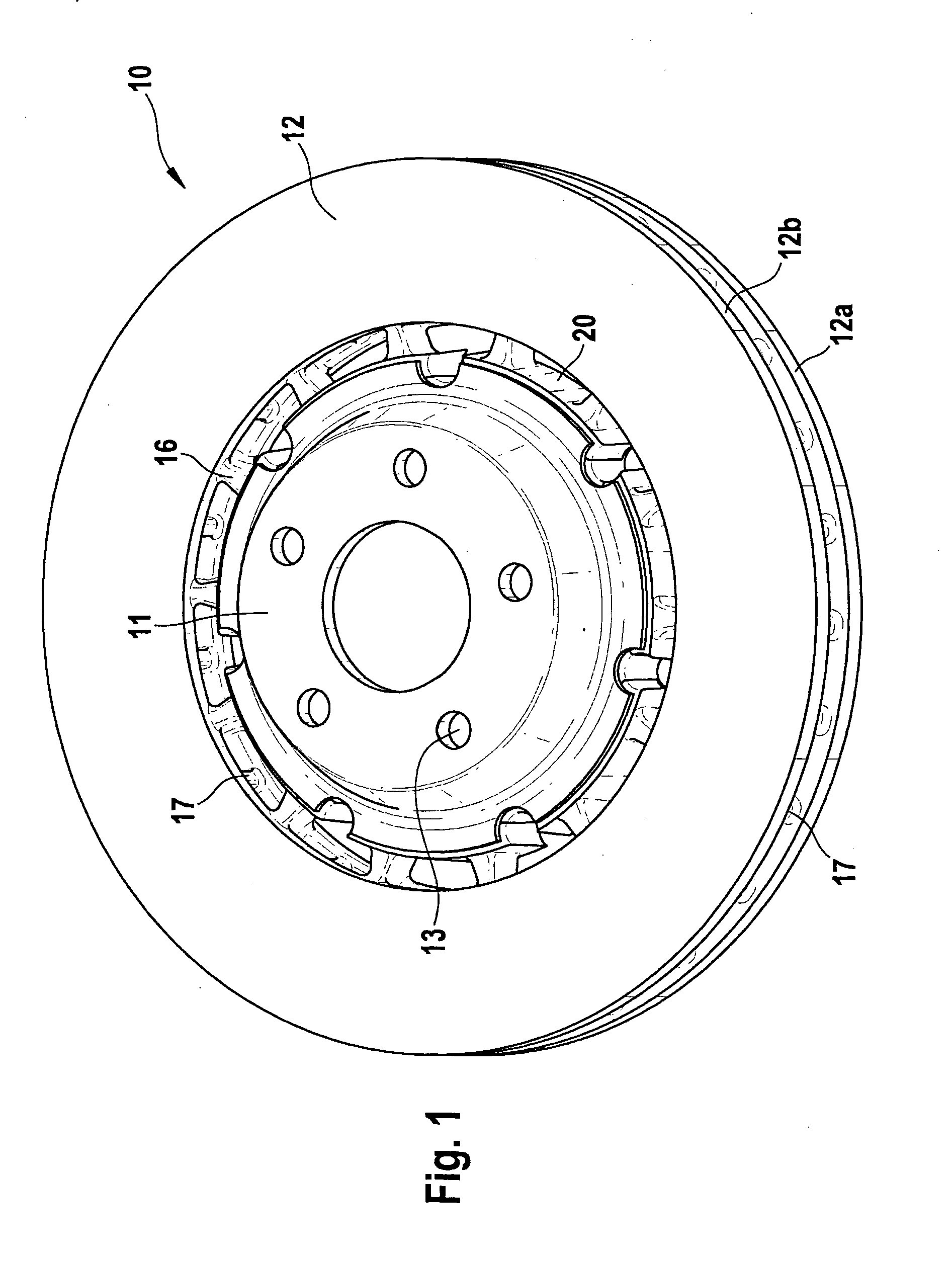
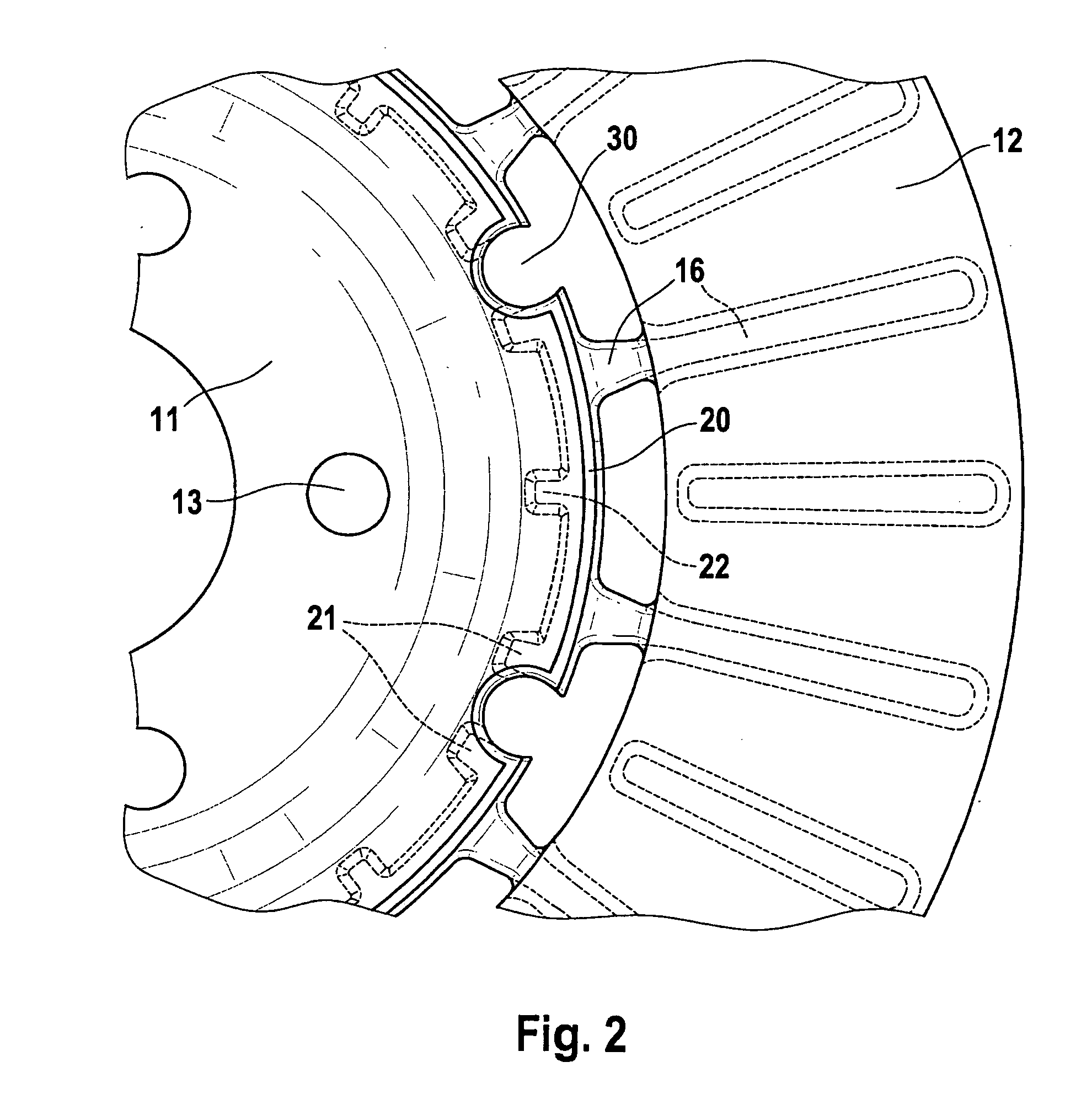
[0010]In FIG. 1, 10 designates a brake disk made up of a disk chamber 11 and a friction ring 12. A disk chamber 11 is fastened to a hub of a vehicle, in a manner not shown here, the screws for fastening it extending through boreholes 13 of disk chamber 11. Friction ring 12 is made up of two friction ring halves 12a and 12b, which are connected to each other by a plurality of crosspieces elements 17 that are distributed over the circumference and run particularly in the radial direction, so that a ventilated brake disk is created. Friction ring 12 is situated on disk chamber 11 with the aid of connecting elements 16 of a supporting ring 20 and extensions 21, 22. One integral component is represented by connecting elements 16, extensions 21, 22 and friction ring 12. This component is able to be produced in one operation. It is possible to produce the two friction ring halves 12a and 12b using the crosspieces 17 in one operation. In another operation, supporting ring 20 is produced hav...


PUM


Abstract

A brake disk includes a disk chamber and a one-piece component made up of a friction ring having connecting links, a supporting ring and extensions developed on the supporting ring. In order to prevent cracking caused by tensile stresses, which may occur during the temperature increase in response to braking, recesses are developed at the transition between the supporting ring and the disk chamber.

Description

BACKGROUND OF THE INVENTION[0001]1. Field of the Invention[0002]The present invention relates to a brake disk, e.g., a ventilated brake disk having a friction ring and a supporting structure connected to the friction ring via connecting links, e.g., a disk chamber.[0003]2. Description of Related Art[0004]A ventilated brake disk is known from published German patent application document DE 43 32 951 A1, which has a friction ring and a supporting structure connected to the friction ring using connecting links. The connecting links are especially developed as pins, bolts or the like, and are positioned over the circumference of the supporting structure. The connecting links project into recesses in the circumferential wall of the friction ring. In the case of larger braking torques, there is a danger that, based on the free length of the connecting links, that is, based on the distance between supporting structure and friction ring, the connecting links, might bend and, in the extreme ...

Claims


Application Information

Patent Timeline
IPC IPC(8): F16D65/12F16D65/847
CPCF16D65/123F16D2065/1344F16D2250/0015F16D2200/003F16D2200/0013
Inventor MUELLER, HANS-WALTER
Owner ROBERT BOSCH GMBH
Why Eureka
Try Eureka