
Lens barrier device, lens barrel, and imaging device

Inactive Publication Date: 2010-07-01
SONY CORP
View PDF15 Cites 4 Cited by
  • Summary
  • Abstract
  • Description
  • Claims
  • Application Information

AI Technical Summary

Benefits of technology

[0010]It is therefore desirable to provide a lens barrier device, a lens barrel, and an imaging device capable of preventing damages on the members and advantageous in enhancing durability.
[0015]It thus becomes possible to prevent damages on members included in the oscillating mechanism, such as the drive ring, which is advantageous in enhancing the durability.

Problems solved by technology

However, when an object or a finger accidentally touches the barrier blades while the barrier blades are maintained at the close position and the barrier blades are directly and forcedly moved from the close position to the open position, an unreasonable force acts on the members forming the oscillating mechanism and these members may possibly be damaged.
Accordingly, a manner as to how damages on the oscillating mechanism are prevented when the barrier blades are directly and forcedly moved from the close position to the open position is a critical issue for the lens barrier device.

Method used


Image

  • Lens barrier device, lens barrel, and imaging device
  • Lens barrier device, lens barrel, and imaging device
  • Lens barrier device, lens barrel, and imaging device

Examples


Embodiment Construction

[0036]Hereinafter, embodiments according to the present invention will be described with reference to the drawings.

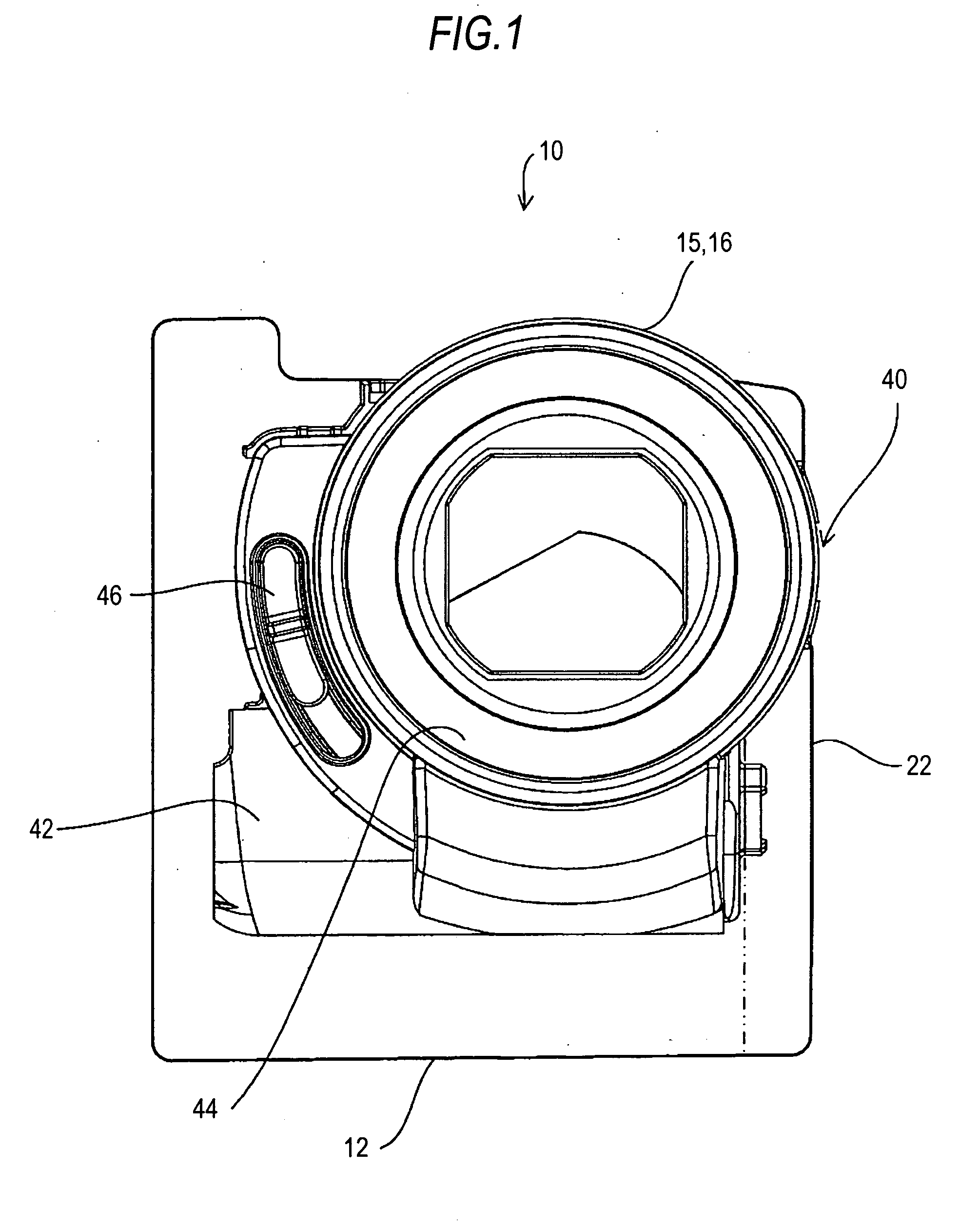
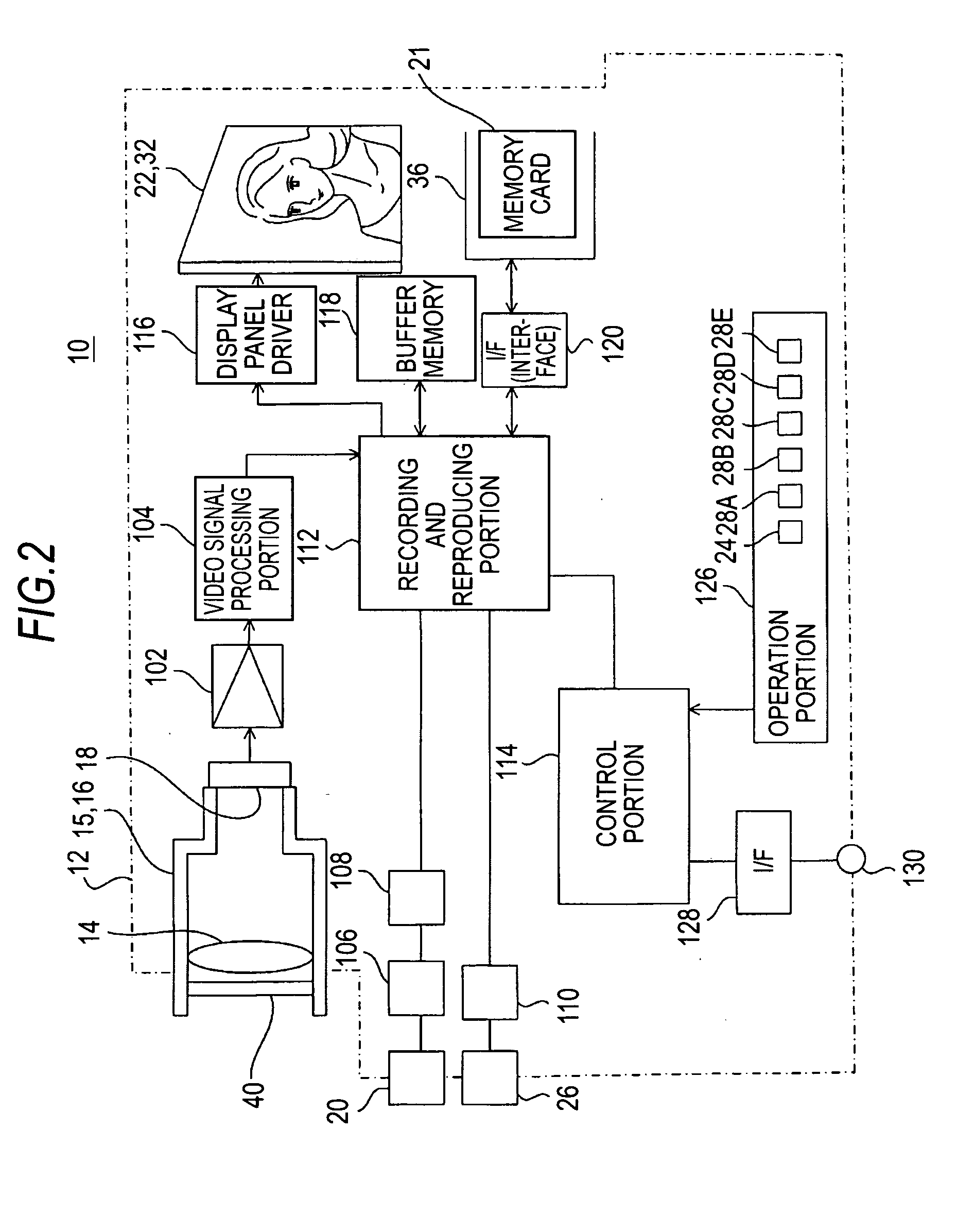
[0037]FIG. 1 is a front view of an imaging device 10 according to an embodiment of the present invention and FIG. 2 is a block diagram showing the configuration of a control system of the imaging device 10.

[0038]Herein, the imaging device 10 is a video camera and it records data, such as captured moving images, still images, and sounds, into a recording medium and reproduces the data from the recording medium.

[0039]Descriptions will be given herein to a case where a memory card 21, which is a plate-shape or a rod-shape recording medium, is used as the recording medium. It goes without saying, however, that a magnetic recording tape, an optical disc, and a hard disk device can be also used as the recording medium and which type of recording medium will be used is the user's option.

[0040]As are shown in FIG. 1 and FIG. 2, the imaging device 10 has a housing 12 that forms ...


PUM


Abstract

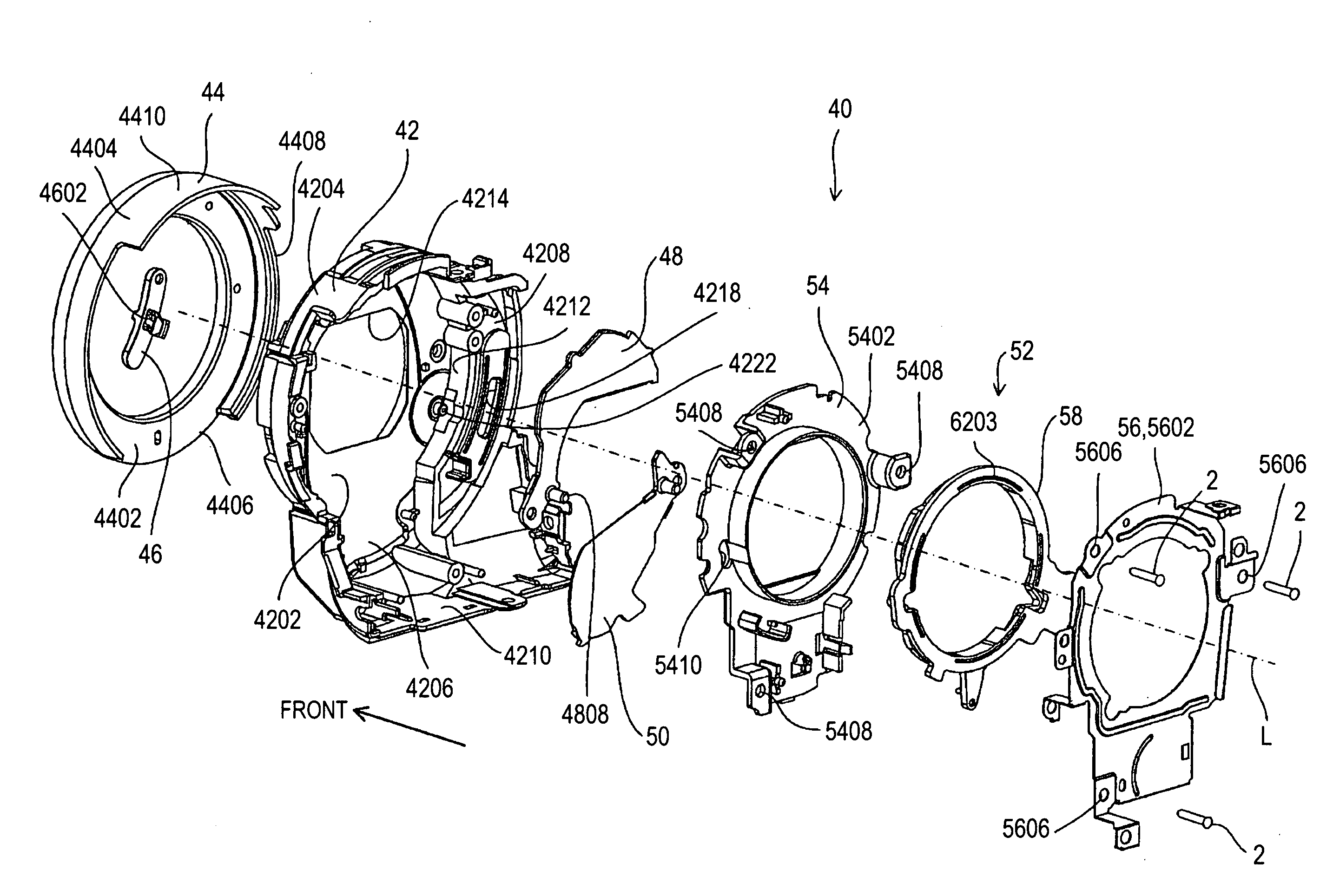
A lens barrier device includes: a plurality of barrier blades disposed in an oscillatible manner in front of an imaging lens positioned in closest proximity to a subject side in an imaging optical system; and an oscillating mechanism that allows the plurality of barrier blades to oscillate so as to form a fully closed state in which an optical path of the imaging optical system is fully closed and a fully opened state in which the optical path is fully opened by the barrier blades. The oscillating mechanism includes a drive ring that is provided in an inversely rotatable manner within a predetermined angular range about an optical axis of the imaging optical system and allows the plurality of barrier blades to oscillate back and forth to form the fully closed state and the fully opened state by rotating forward and backward.

Description

CROSS-REFERENCE TO RELATED APPLICATION[0001]The present application claims priority from Japanese Patent Application No. JP 2008-330419 filed in the Japanese Patent Office on Dec. 25, 2008, the entire content of which is incorporated herein by reference.BACKGROUND OF THE INVENTION[0002]1. Field of the Invention[0003]The present invention relates to a lens barrier device, a lens barrel, and an imaging device.[0004]2. Description of Related Art[0005]For an imaging lens positioned in closest proximity to a subject side in the imaging optical system included in an imaging device, such as a video camera, there has been proposed a lens barrier device that protects the imaging lens from dirt and flaws.[0006]For example, a lens barrier device including a plurality of barrier blades and an oscillating mechanism is described in JP-A-2002-148682.[0007]In this lens barrier device, a plurality of barrier blades are disposed in front of the imaging lens and supported in an oscillatible manner. Th...

Claims


Application Information

Patent Timeline
IPC IPC(8): G03B17/00G02B23/16
CPCH04N5/2254G03B11/043
Inventor KAMATA, YOSHIYUKI
Owner SONY CORP
Learn More