

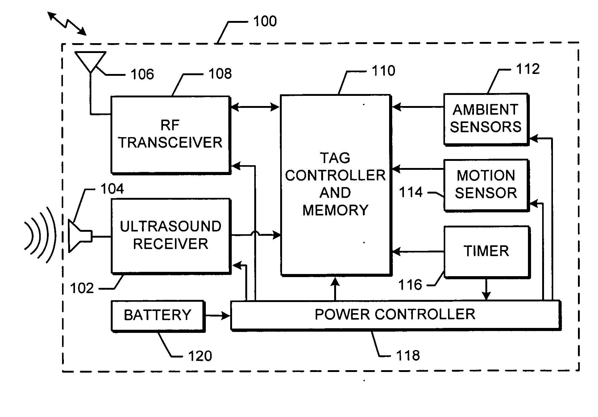
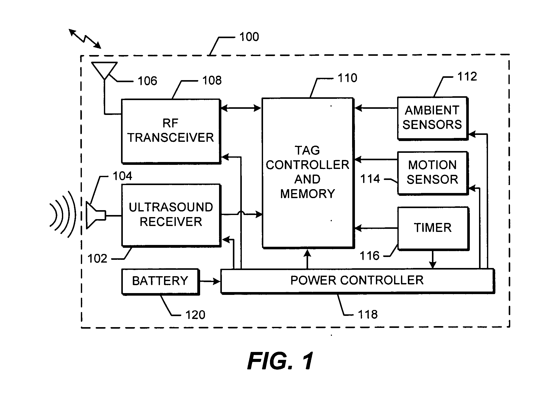
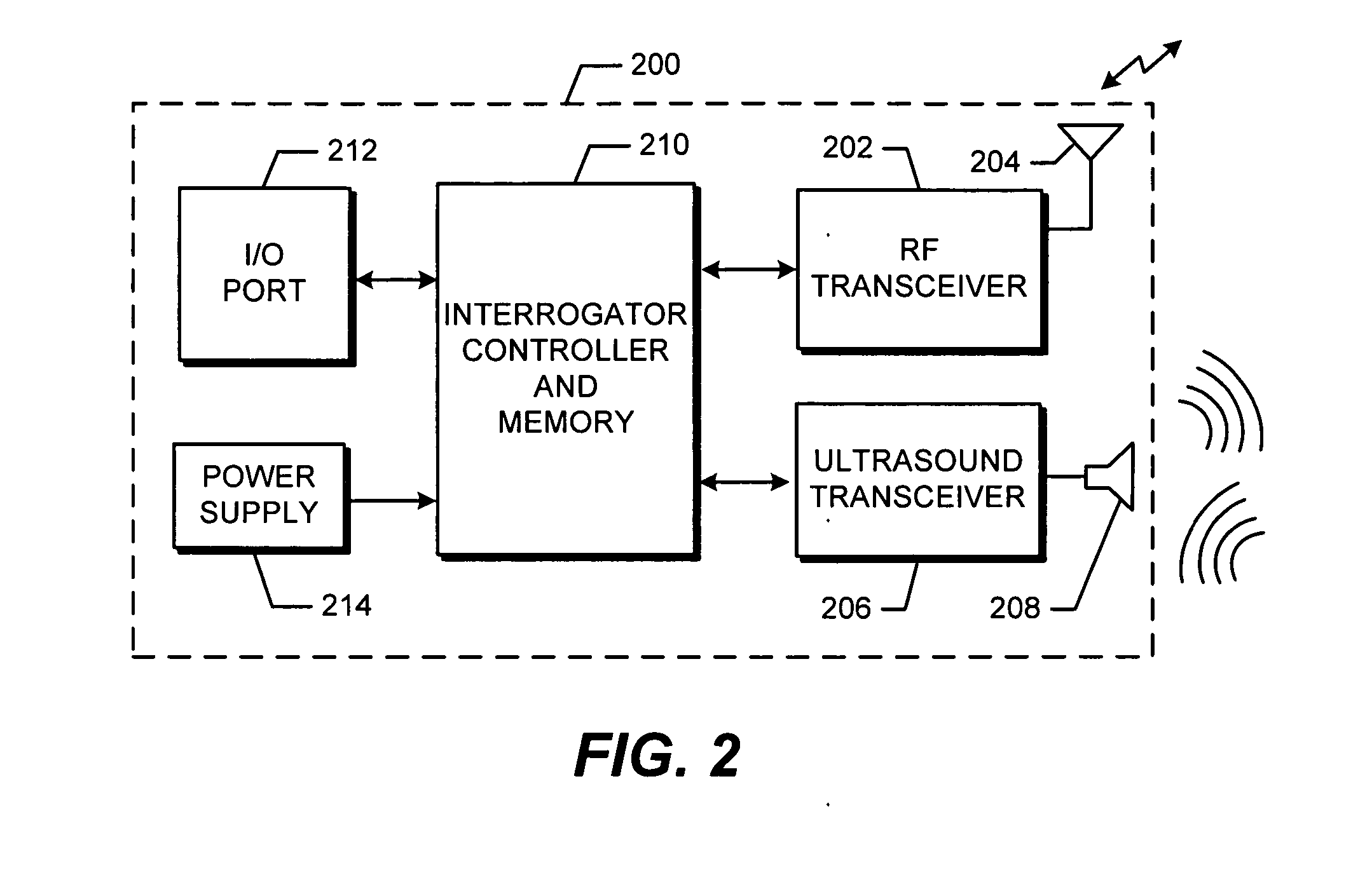
Method and apparatus for localization of RFID tags
a technology of rfid tags and localization methods, applied in the direction of mechanical actuation of burglar alarms, instruments, and using reradiation, can solve the problems of difficult to find a precise tag location to within a few centimeters, less expensive counters operating at lower frequencies have a higher degree of granularity, and passive tags derive their energy
- Summary
- Abstract
- Description
- Claims
- Application Information
AI Technical Summary
Benefits of technology
Problems solved by technology
Method used
Image

Examples
Embodiment Construction
[0022] Aspects of the present invention are advantageous in at least one or more of the following ways.
[0023] Implementations of the present invention improve the accuracy of locating products. The physical locations of products tagged and tracked in accordance with the present invention can be accurately tracked in real time. This is valuable information to retailers interested in keeping their inventories up-to-date and readily locatable. Further, tracking the product positions using RFID tags of the present invention enables the retailer to quickly count the existing stock and locate misplaced items. This allows the retailer to avoid using conventional inventory systems, which are often expensive, labor-intensive, time-consuming, and sometimes inaccurate.
[0024] Tracking the position of tagged items is also advantageous outside the retail environment. For example, there is a need to accurately track the location of portable emergency equipment used in hospitals and other venues....
PUM
 Abstract
Description
Claims
Application Information