Display device for an electronic torque wrench

a technology of electronic torque wrench and display device, which is applied in the direction of force/torque/work measurement apparatus, instruments, manufacturing tools, etc., can solve the problems of increased torque, click noise, and pretension of fasteners

a technology of electronic torque wrench and display device, which is applied in the direction of force/torque/work measurement apparatus, instruments, manufacturing tools, etc., can solve the problems of increased torque, click noise, and pretension of fasteners

US20070119269A1Active Publication Date: 2007-05-31APEX BRANDS

Image

  • Display device for an electronic torque wrench
  • Display device for an electronic torque wrench
  • Display device for an electronic torque wrench

Examples


Embodiment Construction

[0022] Reference will now be made in detail to presently preferred embodiments of the invention, one or more examples of which are illustrated in the accompanying drawings. Each example is provided by way of explanation, not limitation, of the invention. In fact, it will be apparent to those skilled in the art that modifications and variations can be made in the present invention without departing from the scope and spirit thereof. For instance, features illustrated or described as part of one embodiment may be used on another embodiment to yield a still further embodiment. Thus, it is intended that the present invention covers such modifications and variations as come within the scope of the appended claims and their equivalents.

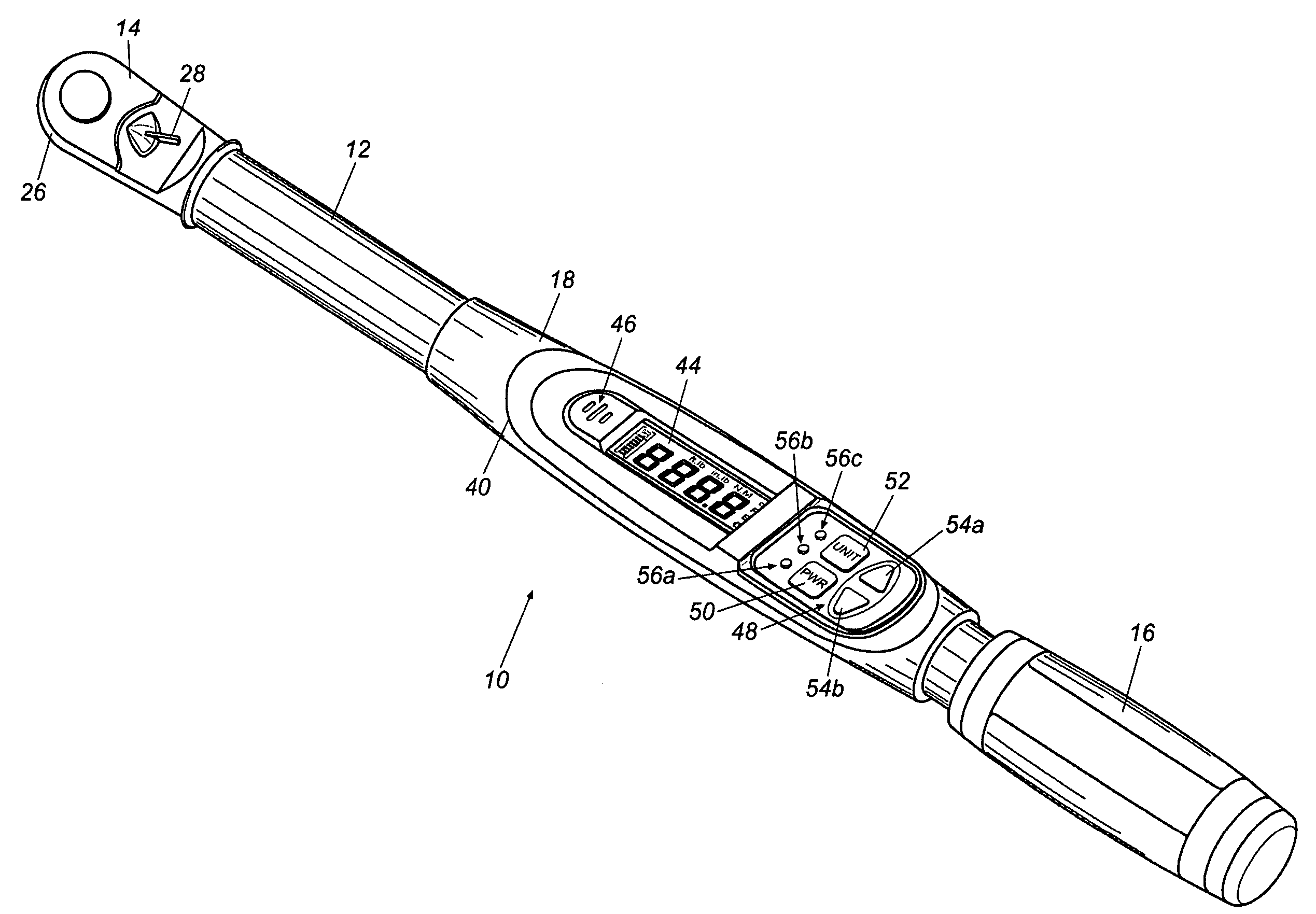
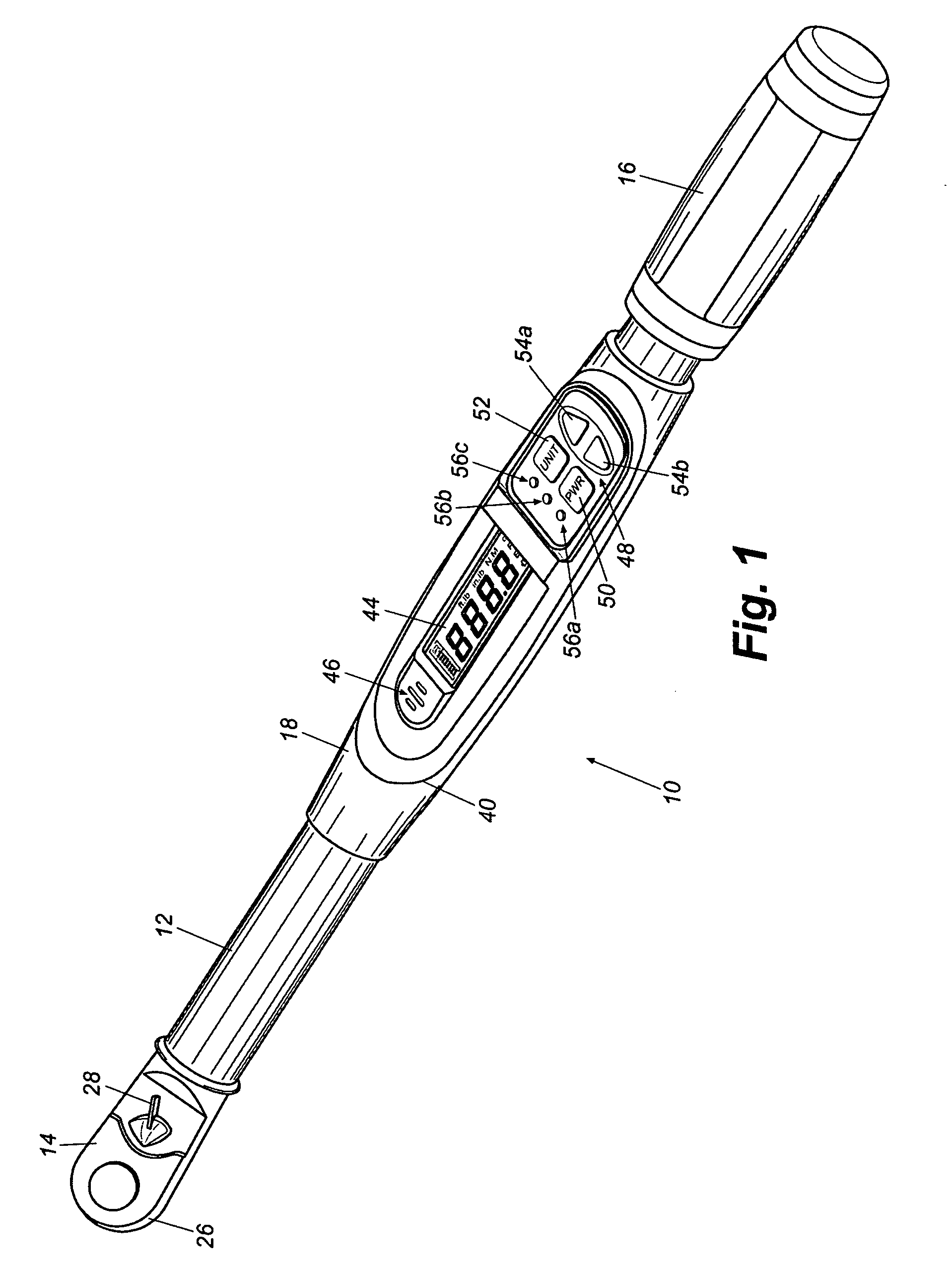
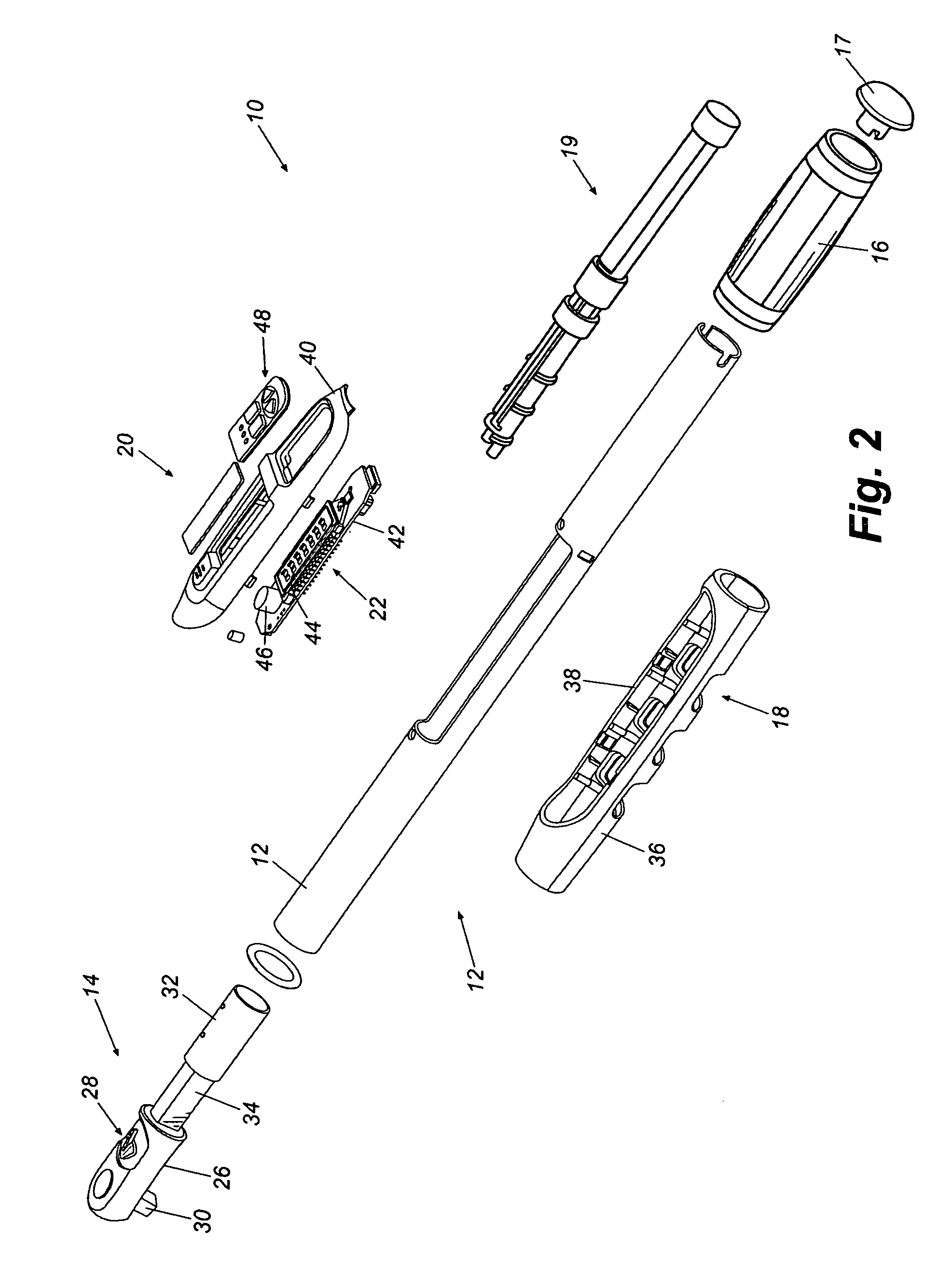
[0023] Referring now to FIGS. 1 and 2, an electronic torque wrench 10 including a temperature compensated simultaneous tracking and peak hold torque display device in accordance with the present invention is shown. The electronic torque wrench 10 includes ...


PUM


Abstract

An electronic torque wrench for engaging a workpiece, the electronic torque wrench including a wrench body and a wrench head disposed on the wrench body, the wrench head being configured to engage the workpiece. A grip handle is disposed on the wrench body opposite the wrench head and a user interface is carried by the wrench body. The user interface includes a digital display with a first readout and a second readout, and an input device for inputting a preset torque value. The first readout displays a peak torque value continuously during operations and the second readout displays an applied torque value continuously during operations.

Description

CLAIM OF PRIORITY [0001] This application claims priority to U.S. Provisional Application 60 / 700,067 filed Jul. 18, 2005.FIELD OF THE INVENTION [0002] The present invention relates generally to torque application and measurement devices. More particularly, the present invention relates to a display device for an electronic torque wrench. BACKGROUND OF THE INVENTION [0003] Often, fasteners used to assemble performance critical components are tightened to a specified torque level to introduce a “pretension” in the fastener. As torque is applied to the head of the fastener, beyond a certain level of torque the fastener begins to stretch. This stretch results in the pretension in the fastener which then holds the components together. A popular method of tightening these fasteners is to use a torque wrench. Accurate and reliable torque wrenches help insure the fasteners are tightened to the proper torque specifications. [0004] Torque wrenches vary from simple mechanical types to sophisti...

Claims


Application Information

Patent Timeline
31 May 2007
Publication
US20070119269A1
IPC
B25B23/14
CPC
B25B23/1425
Inventors
ANJANAPPA, MUNISWAMAPPA; GHARIB, AWAD ALY