Pin Bone Removal Apparatus

a technology of pin bones and removal equipment, which is applied in the field of pin bones removal equipment, can solve the problems of reducing the service life of workers, so as to achieve the effect of reducing the cost of consumer and worker injuries, and reducing the cost of removal

Inactive Publication Date: 2007-05-31
NANOOK INNOVATION
View PDF5 Cites 14 Cited by
  • Summary
  • Abstract
  • Description
  • Claims
  • Application Information

AI Technical Summary

Problems solved by technology

However, since salmon and other fish are expensive, removal of the pin bones without extracting substantial quantities of meat is desired.
However, this option is time-consuming and labor-intensive, which results in higher cost to the consumer and potential injuries to the workers, such as, for example, carpal tunnel syndrome.
However, this technique still relies on manual labor and, thus, suffers from the disadvantages discussed above.
This device, however, is bulky and difficult to align with the pin bones.
This rotatable cylinder design has drawbacks.
One problem is that when the operator moves the cylinder across the fillet, it obscures the area where the bones are picked up.
Consequently, the pin bones are easily flattened so that the cylinder does not catch the bones, hindering the operator from removing all the bones and requiring the operator to repeat the process.
Another potential problem is that the operator pressing the rotating cylinder against the fillet may potentially remove meat from the fillet and create a less appealing appearance.
Additionally, the removed pin bones may become stuck in the cylinder holes used to remove the pin bones, which may eventually require an interruption in operation to clean the cylinder.
In conjunction, thoroughly cleaning the device can be time-consuming and cumbersome.
Cost is another drawback of the rotating cylinder design.
One problem with this design is that the pin bones may get lodged in the gaps of the disks and have to be manually removed.
Still another need in the art is for a device that reliably extracts the pin bones without removing a significant amount of meat from the fillet, creating an unattractive surface appearance, or otherwise damaging the fillet.

Method used


Image

  • Pin Bone Removal Apparatus
  • Pin Bone Removal Apparatus
  • Pin Bone Removal Apparatus

Examples


Embodiment Construction

[0028] The present invention is more particularly described in the following exemplary embodiments that are intended as illustrative only since numerous modifications and variations therein will be apparent to those skilled in the art. As used herein, “a,”“an,” or “the” can mean one or more, depending upon the context in which it is used. The preferred embodiments are now described with reference to the figures, in which like reference characters indicate like parts throughout the several views.

[0029] Ranges may be expressed herein as from “about” one particular value, and / or to “about” another particular value. When such a range is expressed, an alternate embodiment includes from the one particular value and / or to the other particular value. Similarly, when values are expressed as approximations, by use of the antecedent “about,” it will be understood that the particular value forms another embodiment.

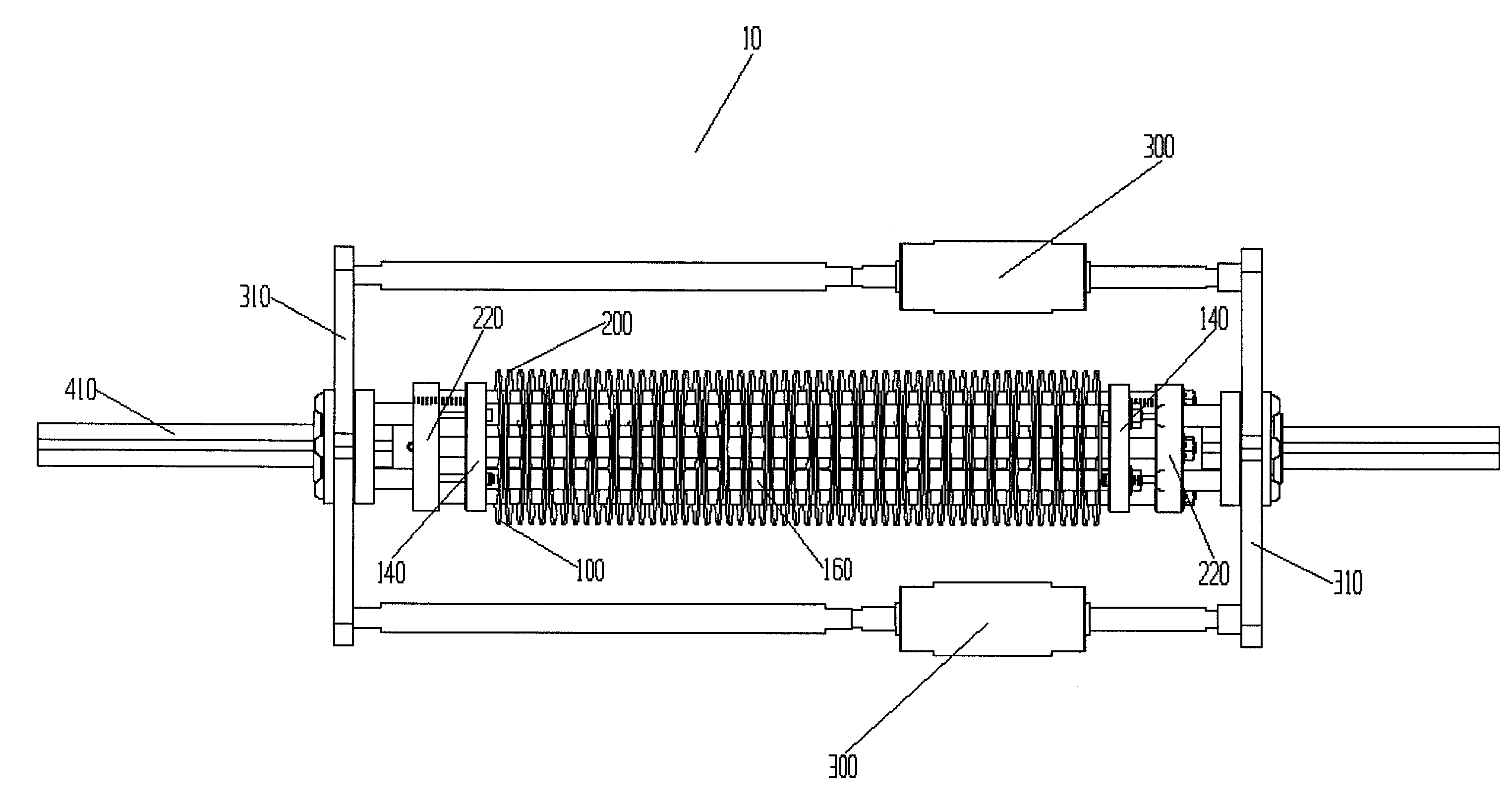
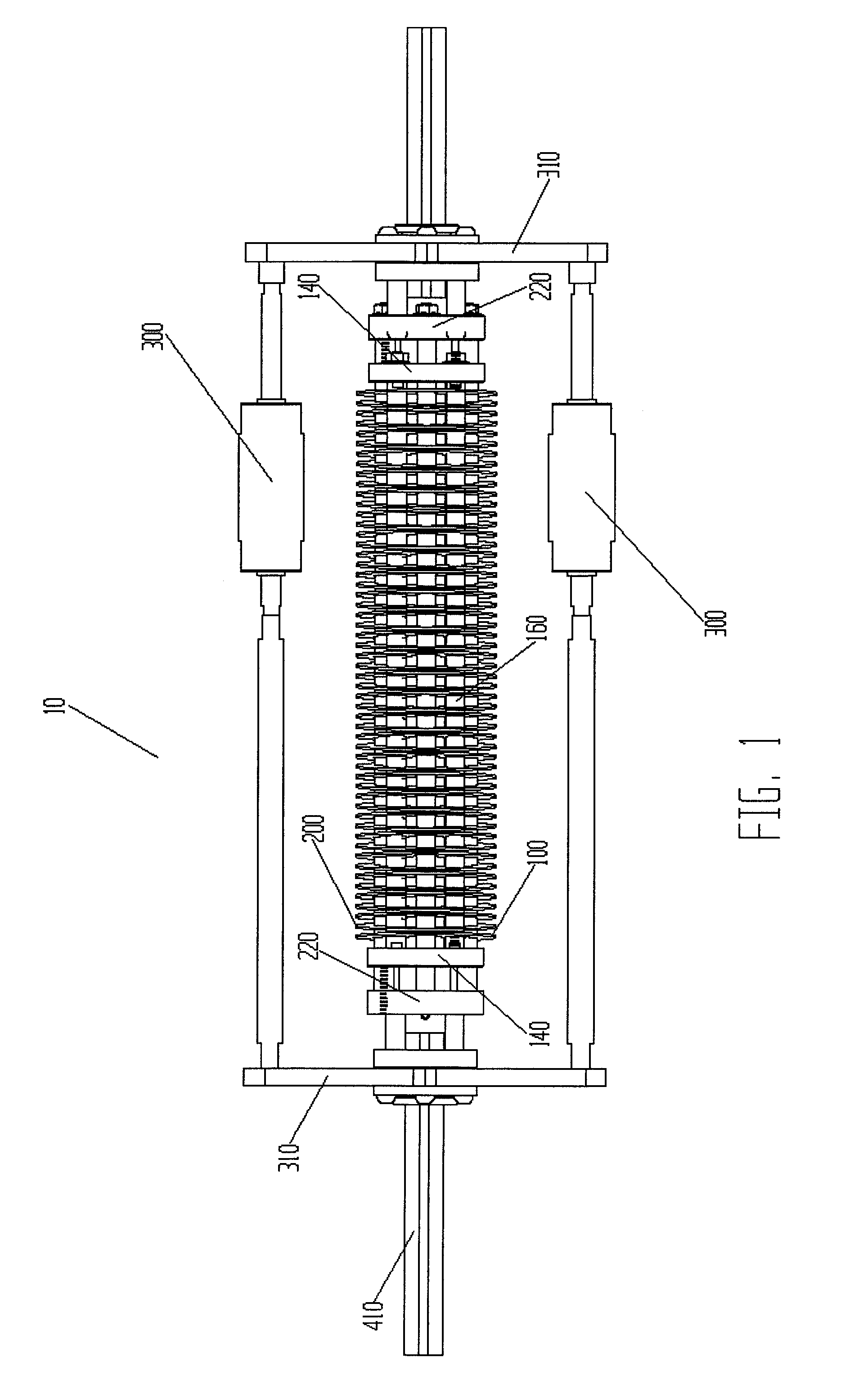
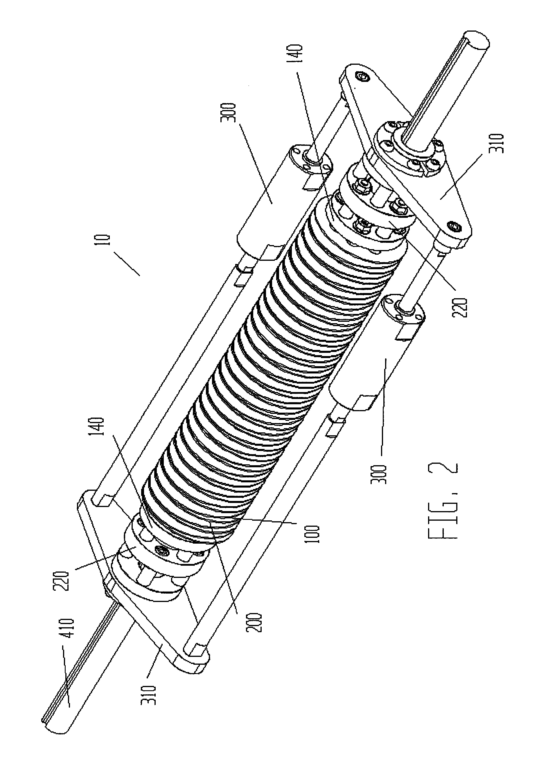
[0030] Referring to the figures, the present invention is a pin bone removal de...


PUM


Abstract

A pin bone removal device that provides a plurality of fixed members arranged substantially in side-by-side orientation. The invention also comprises a plurality of moveable members also substantially arranged in a side-by-side orientation. In one aspect, the fixed members and moveable members collectively form a stack of members in which a moveable member is positioned adjacent each fixed member. In this aspect, a linear drive is operatively connected to each of the moveable members and is configured to cause oscillating movement of each moveable member to cause the moveable members to contact the adjacent fixed member. This movement causes pinch points to be created and released between the fixed and moveable members. As the fillet of fish is moved along the stack of members, the pin bones are caught at each pinch point and then released.

Description

PRIORITY INFORMATION [0001] This application claims the benefit of and priority to U.S. Application No. 60 / 737260, filed on Nov. 16, 2005, which is incorporated herein in its entirety by reference.FIELD OF THE INVENTION [0002] The present invention relates to a device and method for removing bones from a fish and, more specifically, for removing pin bones from a fillet of salmon, pollack, mackerel, trout, whitefish, haddock, scrod, and the like. BACKGROUND OF THE INVENTION [0003] Fish possess a skeletal structure that has a vertebral column or back bone from which spines extend upwardly (dorsal spines) and downwardly (ventral spines). No ventral spines are located in the region of the fish's belly cavity, however. Vertebrae extend over the top of the belly cavity for a short distance on either side of the mid-line, from which rib bones depend and curve downwardly to enclose the belly. Pin bones extend horizontally from the rib bones and terminate at or near the skin. For example, th...

Claims


Application Information

Patent Timeline
Patent Type & Authority Applications(United States)
IPC IPC(8): A22C25/16
CPCA22C25/166
Inventor SHIPMAN, GREGORY
Owner NANOOK INNOVATION
Why Eureka
Try Eureka