Off-set bone plates

Inactive Publication Date: 2007-05-31
FIRST COMMERCE BANK
View PDF22 Cites 33 Cited by
  • Summary
  • Abstract
  • Description
  • Claims
  • Application Information

AI Technical Summary

Benefits of technology

[0011] The protrusions of adjacent longitudinal plates and/or center plates within the bone plate assembly may be mutually opposed or have surfaces, such as inward walls, juxtaposed with one another thereby establishing an off-set section adjacent to, or preferably within, the window a

Problems solved by technology

However, with a DCP plate, only slight and not easily controllable movements occur.
In addition, the bone is pulled at an

Method used


Image

  • Off-set bone plates
  • Off-set bone plates
  • Off-set bone plates

Examples


Embodiment Construction

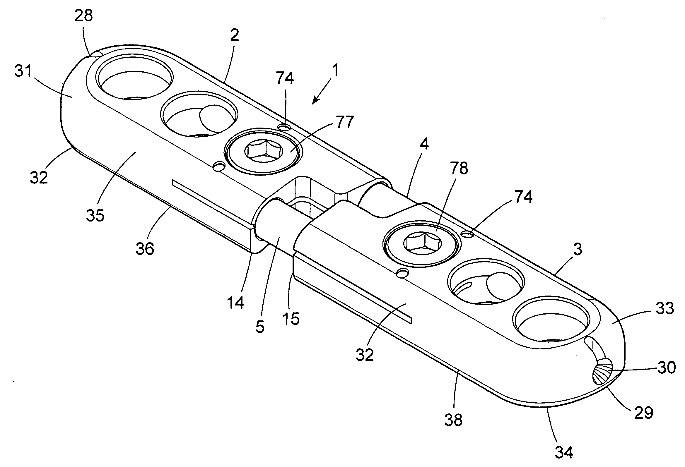
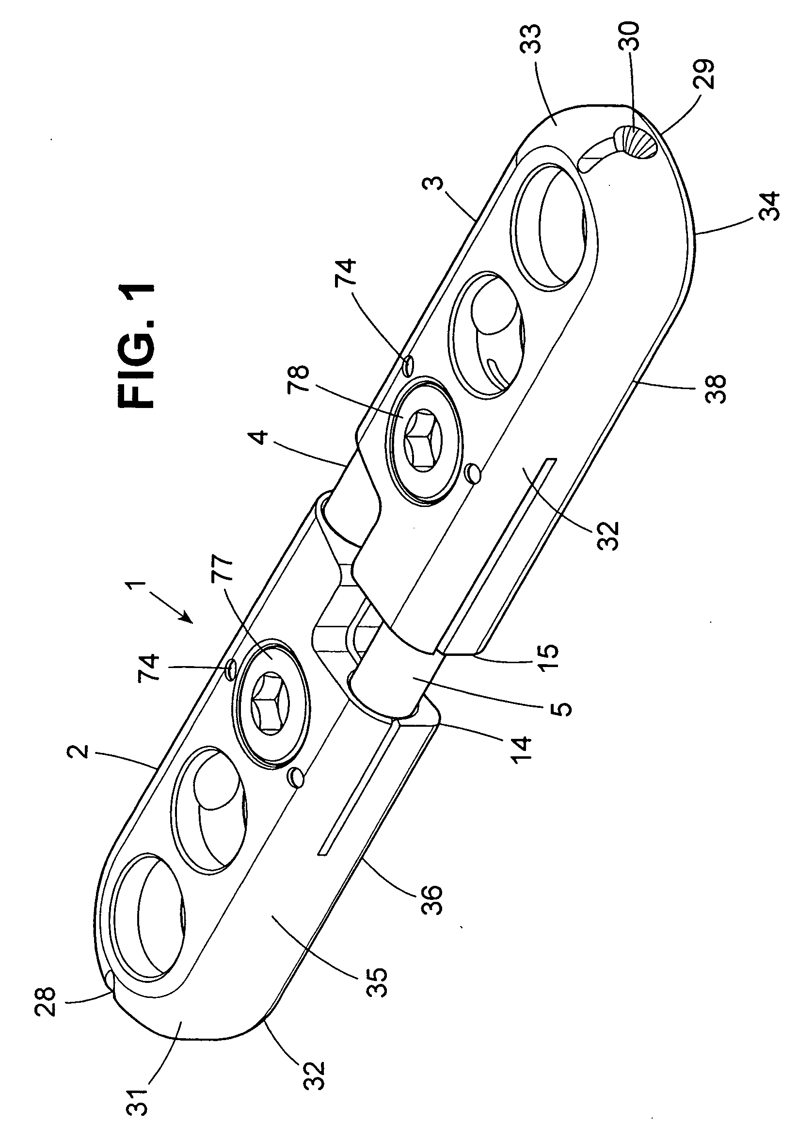
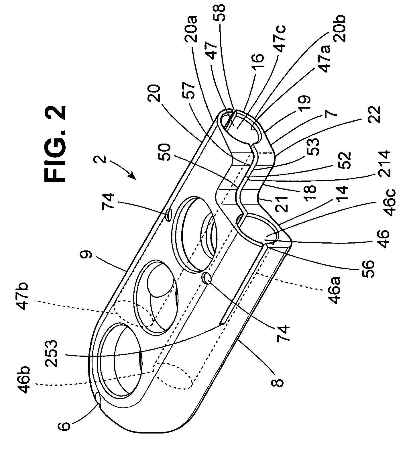
[0036]FIG. 1 illustrates a bone plate 1 in accordance with an embodiment of the invention comprising a first longitudinal plate 2, a second longitudinal plate 3, a distal connecting rod 4 and a forward connecting rod 5. As shown FIG. 2, the first longitudinal plate 2 has a first end 6, a second end 7, a forward side 8 and a distal side 9. The second longitudinal plate, as shown in FIG. 3, also comprises a first end 10, a second end 11, a forward side 12 and a distal side 13.

[0037] The second end of each of the first longitudinal plate and second longitudinal plate comprises a recessed edge (shown as 14 with respect to the first longitudinal plate and 15 with respect to the second longitudinal plate) and a protrusion (shown as 16 with respect to the first longitudinal plate and 17 with respect to the second longitudinal plate). Each protrusion comprises an inward wall adjacent to the recessed edge, an end wall adjacent to the inward wall, which may be about perpendicular, or perpend...


PUM


Abstract

Longitudinal plates and center plates for a bone plate assembly which comprise one or more protrusions. The bone plate assemblies comprise longitudinal plates and optional center plates with connecting rods and further have observation windows and protrusions. Also, methods for treating broken bones of a patient by applying the longitudinal plates and center plates.

Description

BACKGROUND OF THE INVENTION [0001] 1. Field of the Invention [0002] The invention pertains to bone plates, and longitudinal plates and center plates that are components of the bone plates, which have off-set sections. The longitudinal plates and center plates which, in part, form the structure of the bone plates have at least one end which contains a protrusion, and when the longitudinal plates and center plates are joined together by connecting rods, the protrusions of adjacent longitudinal plates and center plates are mutually opposed, and the protrusions, in part, stop excess twisting of the bone plate when applied to the broken bone of a patient. The bone plates further comprise one or more observation windows which allow a surgeon to observe the location of a broken bone while moving the pieces of broken bone together. [0003] 2. The Related Art [0004] Conventional bone plates have fixed dimensions and multiple holes for accommodating bone screws. Surgeons generally use bone pla...

Claims


Application Information

Patent Timeline
IPC IPC(8): A61F2/30
CPCA61B17/8023A61B17/56A61B17/58A61F2/30
Inventor RALPH, JAMES D.TATAR, STEPHEN L.TROXELL, THOMAS N.
Owner FIRST COMMERCE BANK
Why Eureka
Try Eureka