Shear with replaceable shearing tip

a shearing tip and heavy duty technology, applied in the field of shears, can solve the problems of high high maintenance costs, and high cost of replacement of the tip, and achieve the effect of reducing maintenance costs and downtim

Inactive Publication Date: 2007-06-14
CATERPILLAR WORK TOOLS
View PDF12 Cites 45 Cited by
  • Summary
  • Abstract
  • Description
  • Claims
  • Application Information

AI Technical Summary

Problems solved by technology

Such jaw tips are subject to extreme wear and accordingly require frequent replacement.
Replacement of the tips is expensive both from the standpoint of the cost of the tip and the down time required to remove, repair and reconnect a damaged or worn tip or, if beyond repair, to replace with a new tip component.
Accordingly, repairing or replacement of the tip is required each time the piercing and cutting edges become worn or damaged, whereby maintenance costs and down time are undesirably high.
In addition, high lateral forces are exerted on the tip, great tension is also exerted upon the tip, and direct shear bearing loads are also applied to the tip when shearing.
In addition, the shearing tip of 2004 / 0093739 is mounted to the upper jaw by screws, and those screws may easily break off the upper jaw.

Method used


Image

  • Shear with replaceable shearing tip
  • Shear with replaceable shearing tip
  • Shear with replaceable shearing tip

Examples


Embodiment Construction

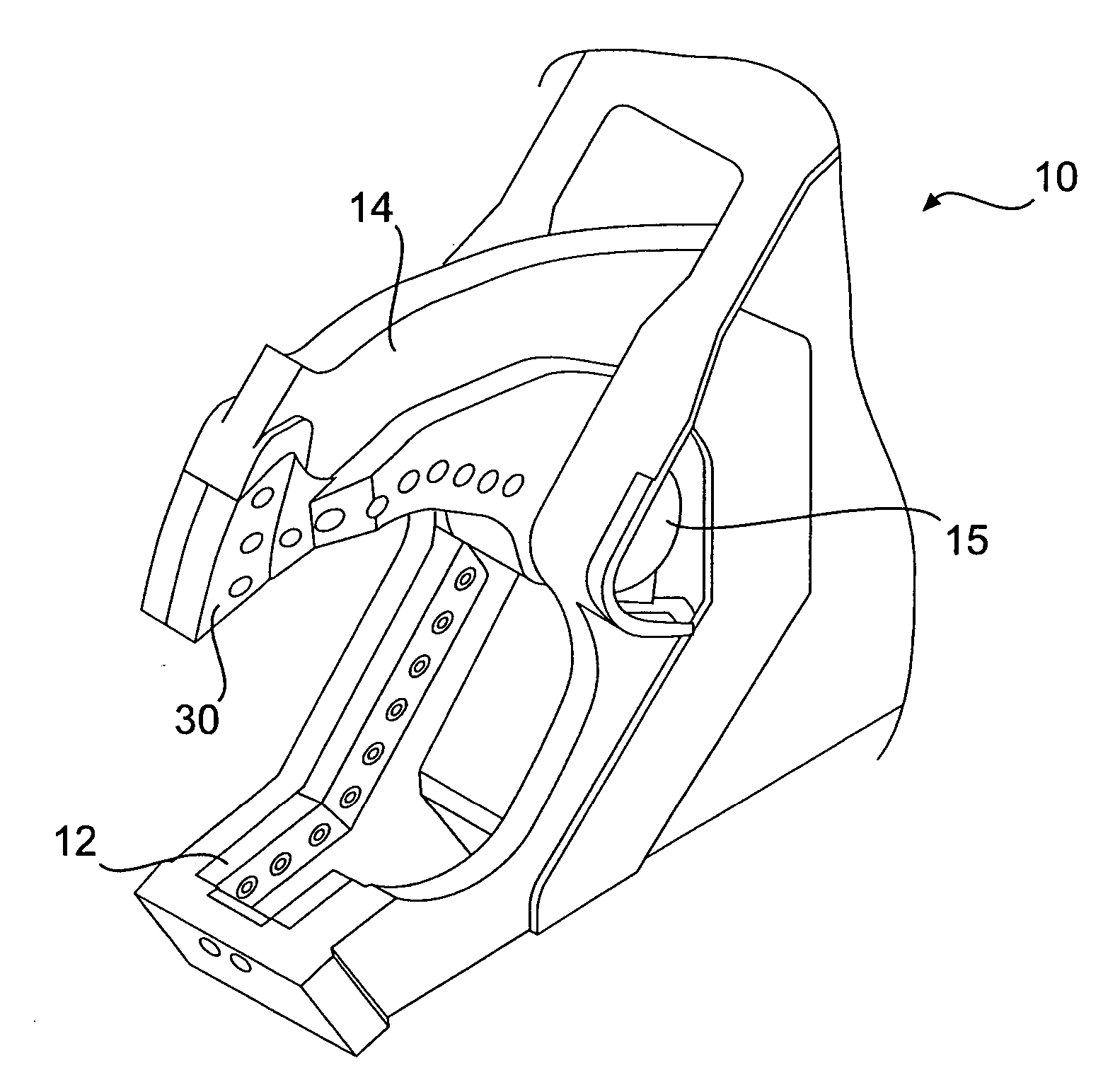
[0013]FIG. 1 illustrates an exemplary shear 10. The shear 10 may be a metal demolition shear or a scrap shear. The shear may be attached to the boom structure of, for example, excavating or earth-moving excavation equipment. The shear 10 comprises a fixed or stationary lower jaw 12, a movable upper jaw 14, and a pivot 15 pivotally connecting the lower jaw 12 and the upper jaw 14.

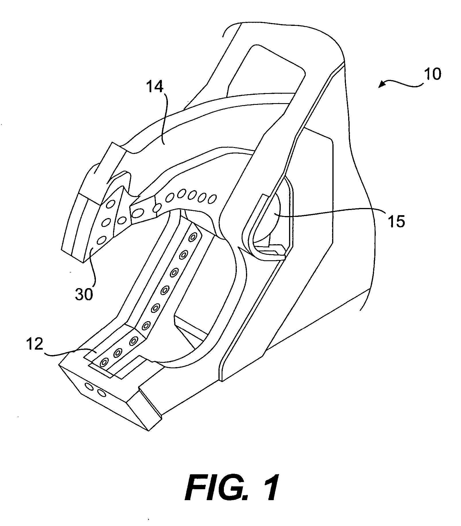
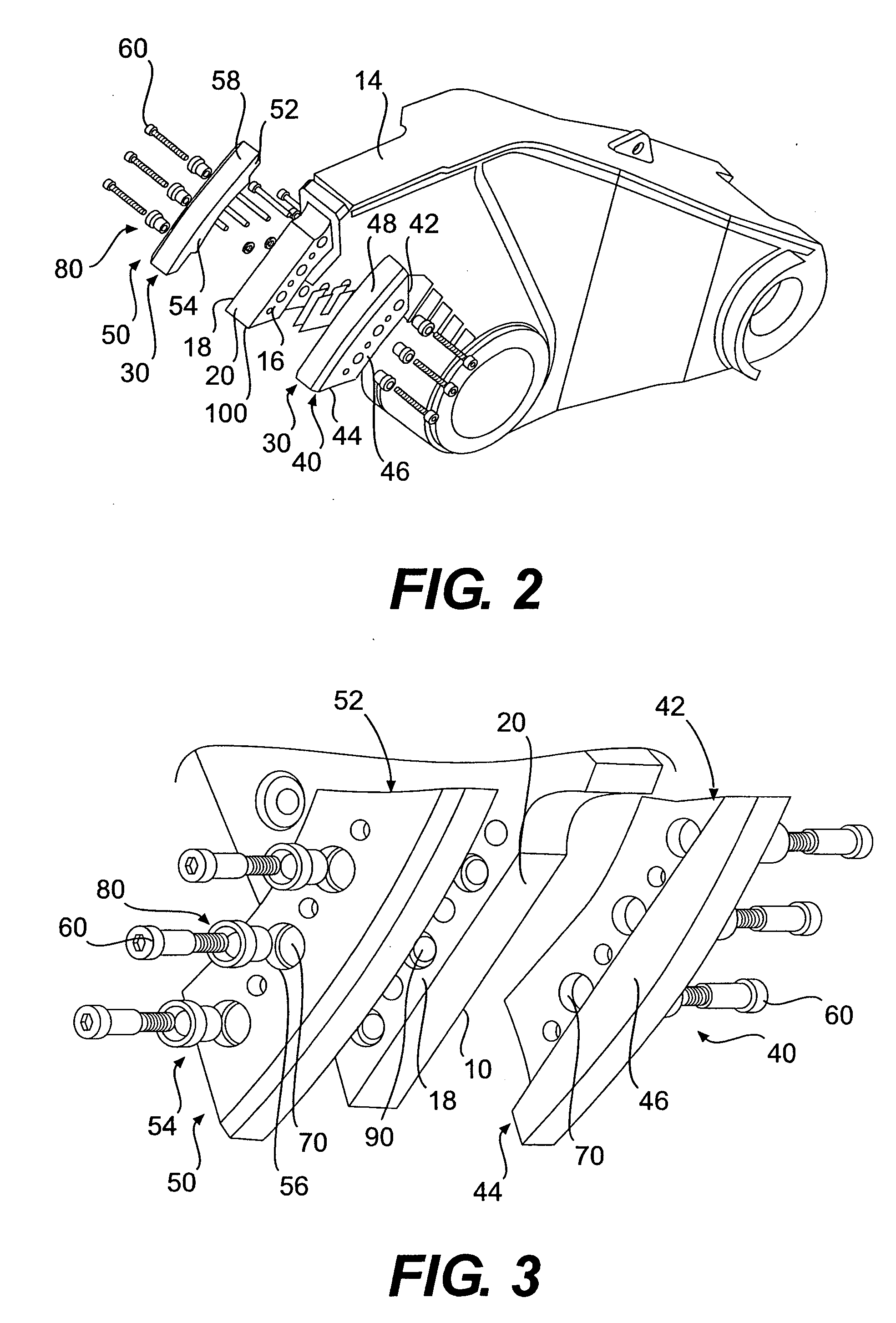
[0014]FIGS. 2 and 3 illustrate an exemplary replaceable shearing tip 30 for using with the shear 10. The upper jaw 14 has a left portion 16, a right portion 18, and a front portion 20 between the left portion 16 and the right portion 18. The replaceable shearing tip 30 has a left part 40 and a right part 50. The right part 50 and the left part 40 are interchangeable. In one embodiment, the left part 40 and the right part 50 are substantially identical. The left part 40 has two symmetrical edges including an upper edge 42 and a lower edge 44, a mounting section 46 extending between the two symmetrical edges ...


PUM

PropertyMeasurementUnit
L-shapeaaaaaaaaaa
tensionaaaaaaaaaa
shearing areaaaaaaaaaaa

Abstract

A replaceable shearing tip is provided for using with a shear, the shear having a lower jaw and an upper jaw pivotally connected to the lower jaw, the upper jaw having a left portion, a right portion, and a front portion between the left portion and the right portion. The replaceable shearing tip has a left part having two edges, a mounting section extending between the two edges for mounting the left part on the upper jaw, and a front section connected to the mounting section for covering the front portion of the upper jaw. The replaceable shearing tip further has a right part, wherein the left part and the right part are interchangeable.

Description

TECHNICAL FIELD [0001] The present disclosure is directed to a shear, and more particularly, to a heavy duty shear having a replaceable shearing tip. BACKGROUND [0002] A conventional heavy duty shear typically employs relative movable upper and lower jaws with shear blades of hardened steel on both the upper jaw and the lower jaw. The distal end of the jaw members is provided with a cutting and piercing tip by which a workpiece is pierced and severed during closure of the one jaw member relative to the other. Such jaw tips are subject to extreme wear and accordingly require frequent replacement. Replacement of the tips is expensive both from the standpoint of the cost of the tip and the down time required to remove, repair and reconnect a damaged or worn tip or, if beyond repair, to replace with a new tip component. Accordingly, repairing or replacement of the tip is required each time the piercing and cutting edges become worn or damaged, whereby maintenance costs and down time are...

Claims


Application Information

Patent Timeline
Patent Type & Authority Applications(United States)
IPC IPC(8): B25F3/00
CPCB23D31/008B23D35/002B23D35/008E02F3/965E04G23/082
Inventor GRANT, PATRICKGEMERT, JOHN VAN
Owner CATERPILLAR WORK TOOLS
Why Eureka
Try Eureka