Cable installation

a cable installation and cable technology, applied in the field of cable installation, can solve the problems of increasing the cost of installing cable, and increasing the difficulty of installation

Active Publication Date: 2007-06-21
PRYSMIAN CABLES & SYST
View PDF7 Cites 21 Cited by
  • Summary
  • Abstract
  • Description
  • Claims
  • Application Information

AI Technical Summary

Benefits of technology

[0009] The invention also includes an electrical cable fixing kit for use in securing electrical cabling to a structure, and an adapter for a nail gun, said electrical cable clip being arranged to receive and secure at least one electrical cable and being provided with an aperture for a nail by which, in use, said electrical cable clip is secured to said structure, said adapter comprising a body on which said cable clip can be fitted, said body having a through-hole arranged to be in line with said aperture when said clip is fitted to the body, and said through-hole being arranged to receive a nozzle of a nail gun such that said body part can be releasably fixed on said nozzle whereby said electrical cable clip can be placed in a desired position adjacent said structure supported by said nozzle via said adapter to permit a nail to be fired through said nozzle to pass through said aligned through-hole and aperture to secure said electrical cable clip against said structure at said desired position.
[0018] The invention also includes a nail gun having a handle and a part for mounting a fixing for an elongate object on said nail gun, said nail gun having a normal use orientation in which said handle extends in a predetermined direction and said part being movable relative to said handle such that the orientation of said fixing relative to the handle can be set to a desired position, whereby, in use, an installer can vary the orientation of fixings installed using said nail gun with said handle extending said predetermined direction.

Problems solved by technology

This adds to the cost of installing cabling.
A further disadvantage of installing cabling using known clips is that the clip must be fitted around the cable before being secured to the building structure and the installer has to hold the clip in place and provide support for the cable while screwing the screw(s) into its (their) hole(s).
This makes installation more awkward and time consuming.

Method used


Image

  • Cable installation
  • Cable installation
  • Cable installation

Examples


Embodiment Construction

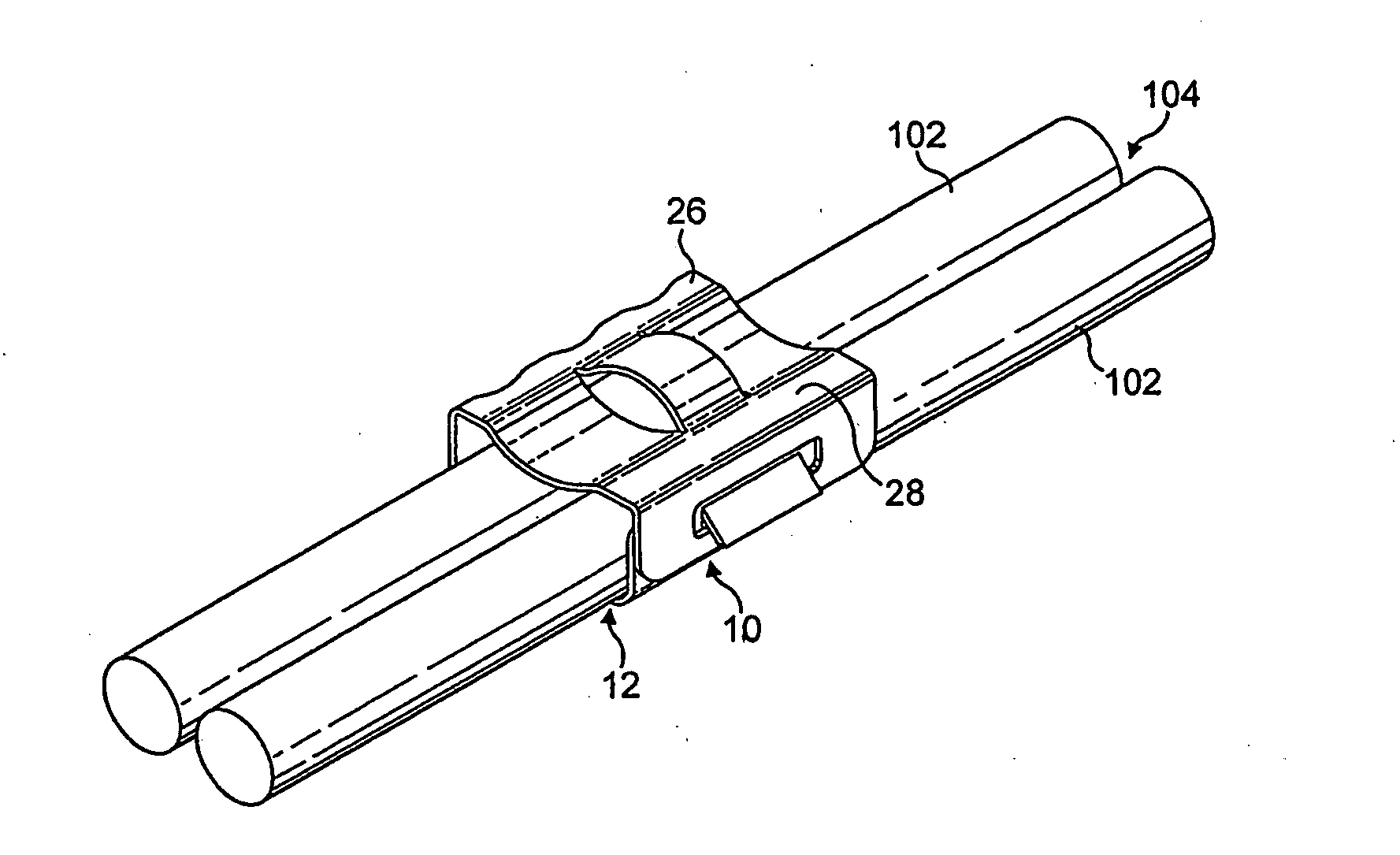
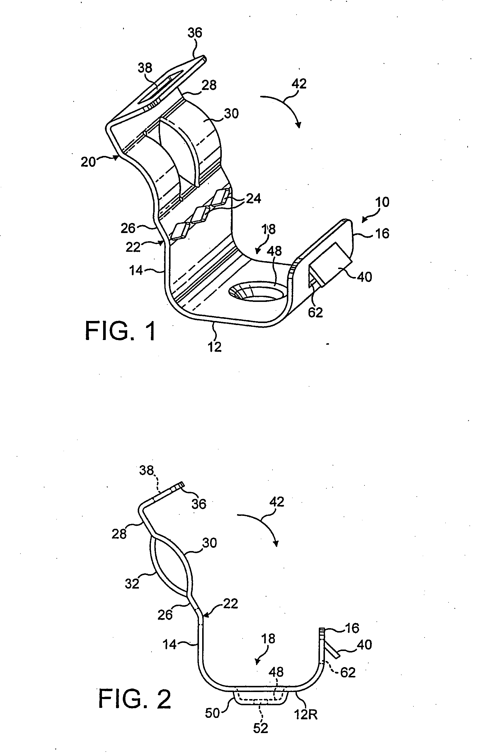
[0028] Referring to FIGS. 1 and 2, an electrical cable clip 10 for securing electrical cabling to a structure, such as the wall of a building or the like, comprises a body comprising a base portion 12 and opposed side walls 14, 16 projecting upwardly from opposite sides of the base portion to define a channel 18 for receiving two electrical cables (as shown in FIG. 7). The sidewalls 14, 16 are curved at their lower ends where they join the base portion 12, such that the channel 18 is generally U-shaped.

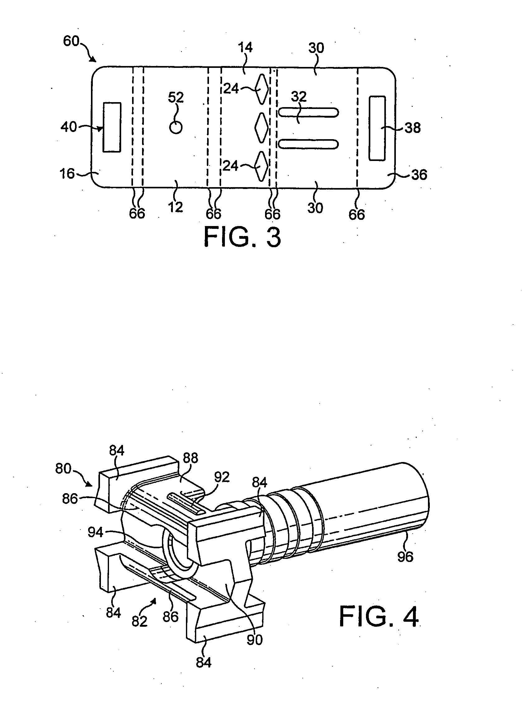
[0029] The electrical cable clip 10 has a closure member 20 that is integral with the sidewall 14. A hinge 22 is defined between the closure member 20 and the sidewall 14 by a series of perforations 24 provided at spaced intervals along the length of the clip where the closure member joins the sidewall 14. The perforations 24 extend further in the lengthways direction of the hinge than in the direction-transverse thereto. That is, the perforations 24 are longer than they are wide. Pr...


PUM

PropertyMeasurementUnit
timeaaaaaaaaaa
angleaaaaaaaaaa
fire resistantaaaaaaaaaa

Abstract

A method of installing electrical cabling by securing an electrical cable clip to a structure using a fixing element that passes through the clip into the structure, subsequently inserting one or more electrical cables into a cable receiving channel defined by the clip and securing the electrical cables in that channel. The structure will typically be the wall of a building or the like and the fixing element is preferably a nail that is fired through the base portion of the electrical cable clip by means of a nail gun.

Description

BACKGROUND TO THE INVENTION [0001] The invention relates to improvements in cable installation and particularly, but not exclusively, to the installation of fire resistant cables. [0002] United Kingdom regulations and standards for fire resistant cable installations require that the cable is fixed to building structures by metallic fixings that maintain their support during a fire. Currently, such cables are installed using a P-shaped metallic clip, which is fitted around the cable and then screwed to the building structure. Typically, one screw is used and is screwed into a pre-drilled hole, which may have to be plugged to accept the screw. If two cables are to be installed side-by-side, an extended U-shaped clip may be used. Such clips are usually secured by means of two screws, one on each side of the cables. As with the P-shaped clip, the clip is fitted around the cables and is then secured to the building structure by means of the two screws. [0003] The typical spacing between ...

Claims


Application Information

Patent Timeline
Patent Type & Authority Applications(United States)
IPC IPC(8): H01B7/00H02G3/32
CPCH02G3/32Y10T24/44556Y10T24/44538Y10T29/49947
Inventor JOURNEAUX, TERRYRAWLINSON, JONATHAN
Owner PRYSMIAN CABLES & SYST
Why Eureka
Try Eureka