Joints

a joint and joint technology, applied in the field of joints, can solve problems such as potential safety hazards

Inactive Publication Date: 2007-06-14
ZEPHYROS INC
View PDF7 Cites 19 Cited by
  • Summary
  • Abstract
  • Description
  • Claims
  • Application Information

AI Technical Summary

Benefits of technology

[0007] Accordingly, a joint device is provided for joining tubular structures. The joint device includes a multi-armed joining piece having two or more arms, each of the arms including a plurality of mating holes. The joint devices also includes two or more plugs configured for insertion within two or more tubular structures, each of the two or more plugs including at least one mating hole. It is also contemplated that one of the plugs can be provided with a collar to limit the extent to which the plug may be inserted into a tubular structure. One of the plugs can also be provided with a head adapted to be positioned outside of the first tubular structure when the first plug is inserted within the first tubular structure. When used, the head is often provided with the at least one mating hole of the plug, which is configured to be aligned with the plurality of mating holes of a first arm of the two or more arms. Moreover, it is contemplated that the two or more plugs are connected to the two or more arms of the joining piece by the provision of pins through one of the plurality of mating holes of each arm of the two or more arms and through the at least one mating hole of each plug of the two or more plugs to form a joint between the two or more tubular structures into which the plugs have been placed.

Problems solved by technology

Joining the structures can however be one of the more difficult aspects of the production of a tubular structure and in particular it can add undesirable weight to the overall structure, it can also provide a point of weakness in a structure perhaps causing a potential safety hazard.

Method used


Image

  • Joints
  • Joints
  • Joints

Examples


Embodiment Construction

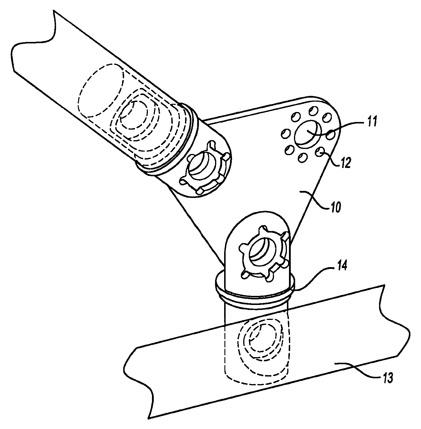
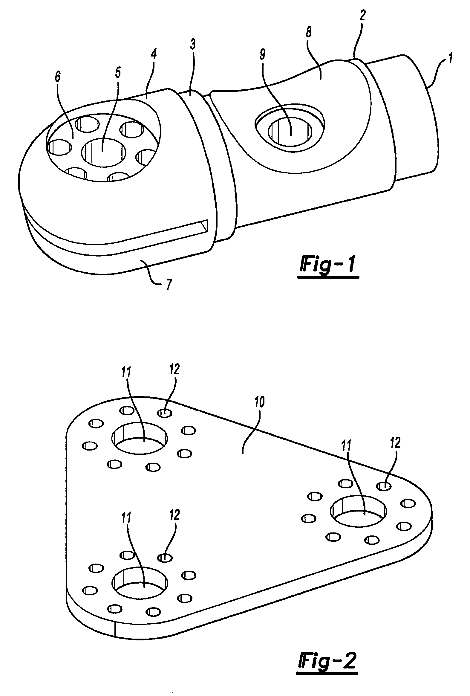
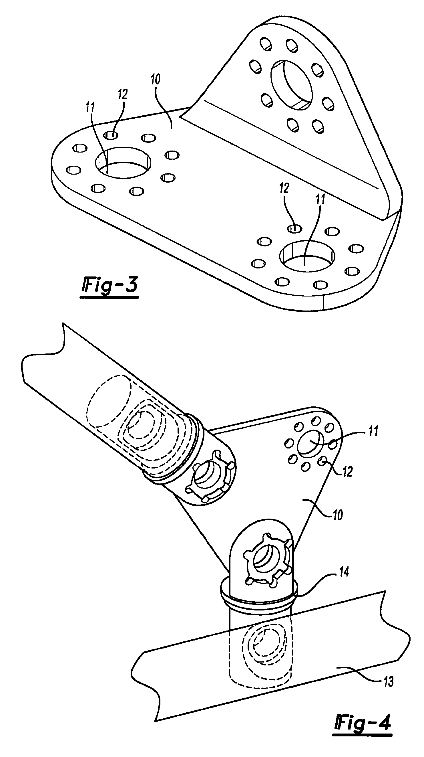
[0017] The present invention therefore provides a means for joining tubular structures comprising a plug for insertion into the tubular structure provided with a collar to limit the extent to which the plug may be inserted into the tubular structure the plug being provided with a head adapted to be positioned outside of the tubular structure when the plug is inserted within the structure the head being provided with a plurality of holes which can be aligned with corresponding holes in a multi armed joining piece whereby two or more plugs can be connected to two or more arms of the joining piece by the provision of pins through the mating holes to form a joint between two or more tubular structures into which the plugs have been placed.

[0018] The plug is preferably provided with a central hole surrounded by a ring of usually smaller holes and the joining piece is provided with a matching set of holes. The plug and the joining piece may thus be linked by a pin passing through the cen...


PUM


Abstract

Improved means for joining tubular structures are provided which consist of a plug for insertion into the tubular structure provided with a plurality of attachment points which can be used to link one or more tubes the plug is provided with a rim of greater cross section that the internal cross section of the tubular structure to control the extent to which the plug can enter the structure.

Description

[0001] The present application claims the benefit of the filing date of U.K. Patent Application 0506513.1 (filed Mar. 31, 2005) the contents of which are hereby incorporated by reference in their entirety. TECHNICAL FIELD [0002] The present invention relates to improvements in or relating to joints and in particular to means for joining tubular structures. BACKGROUND OF THE INVENTION [0003] Tubular structures of varying cross sections are used in a wide range of activities often to provide strength at relatively lightweight. Examples of the use of such structures are in the construction and transportation industries such as in scaffolding, light weight structure in automobiles, trucks and busses to provide reinforcement, hand rails and the like. Other uses are in aircraft including lightweight flying machines such as unmanned surveillance aircraft, microlights, gliders and the like. [0004] In many uses of tubular structures it is necessary to join two or more tubular structures toge...

Claims


Application Information

Patent Timeline
Patent Type & Authority Applications(United States)
IPC IPC(8): F16B7/04E04B1/58
CPCE04B1/585Y10T403/34F16B7/04
Inventor MEYER, FRANCISBIEBER, SERGEMUTEAU, STEPHANE
Owner ZEPHYROS INC
Why Eureka
Try Eureka