For
liquid methane, given that the
specific gravity of the substance is low (d.apprxeq.0.47), the configuration of such tankers is most unusual, and because of the high cost of making thermally insulated tanks, LNG tankers are extremely expensive.
They also require many precautions to be taken in operation since in the event of liquefied gas leaking onto structural elements of the steel
hull of the tanker, the steel becomes brittle and no longer withstands the stresses from the surroundings, leading to the vessel being lost.
Floating structures that are similar but made of concrete have been envisaged because concrete behaves well when put into contact with liquefied gas at very low temperature, however such structures have been designed for sailing purposes and are much bulkier and more massive than vessels made of steel, so the resulting vessels are not economically competitive with equivalent vessels made of steel.
With the techniques commonly used for making barges of concrete structure, giant barge building cannot be extrapolated from the technology used for the Ardjuna barge since that would require either the number of conventional tanks to be multiplied or else tanks to be made that are small in number but gigantic in size, based on free-standing technology, but in that case there would be very great difficulties of implementation, or even technical impossibilities, because of the considerable loads to be transferred via the cradles (isostatic support).
Such giant tanks, for the cryogenic temperatures of liquefied
methane (-165.degree. C.) present significant shortening of the inside wall of the tank when it is cooled down, thus creating differential displacements at the supports between the tank and the structure of the barge, since the structure remains at ambient temperature.
The supports become very difficult to design since they must be capable of accommodating these movements without giving rise to significant levels of stress which could create fatigue phenomena in said supports or in the tank, thus making such a barge dangerous to operate.
Extrapolating such principles to giant tanks working at -165.degree. C. or at even lower temperatures would lead to support systems that are extremely complex, requiring major reinforcement of the concrete
hull and thus requiring very large quantities of
prestressed concrete to be used.
Furthermore, in
spite of the good mechanical behavior of concrete, particularly when in contact with liquefied gas, the risk of micro-
cracking appearing in zones of maximum stress (support cradles) can lead to water infiltrating through the
solid concrete structure, running the risk of corroding the
metal reinforcement inside the concrete and of degrading the performance of the
insulation system, and this has dissuaded the person skilled in the art from using such concrete barges for storing liquefied
methane at sea.
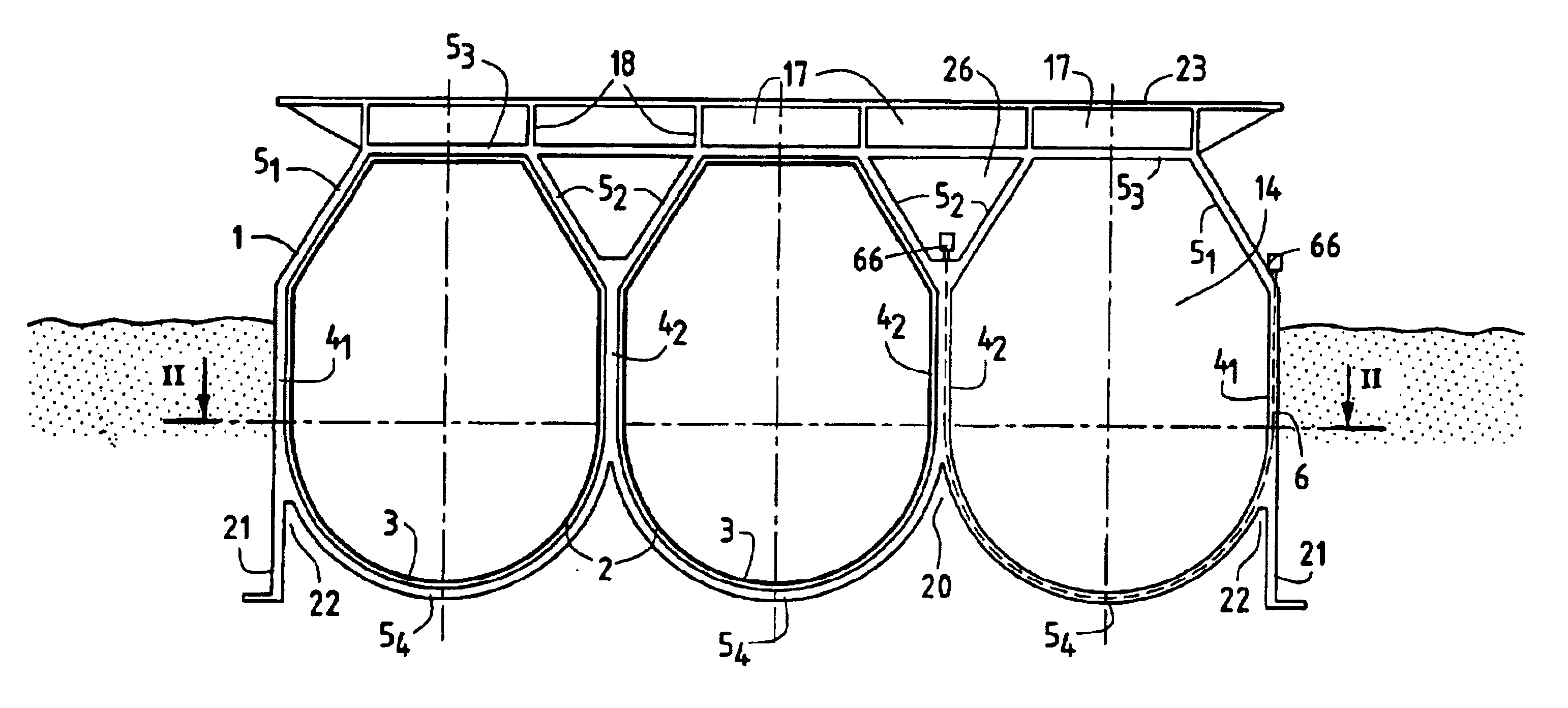
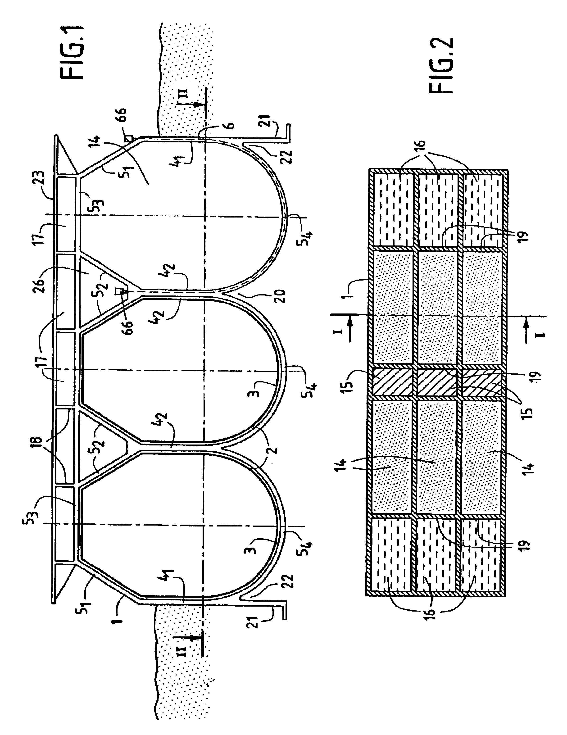
Tanks of that shape having curvature in two directions simultaneously are difficult to make and they also require associated
metal-work structures that are larger and difficult to make since the tanks do not have common side walls enabling the tanks to bear against one another and provide
mutual support when placed side by side.
In addition, such spherical shapes imply that a large quantity of concrete needs to be used.
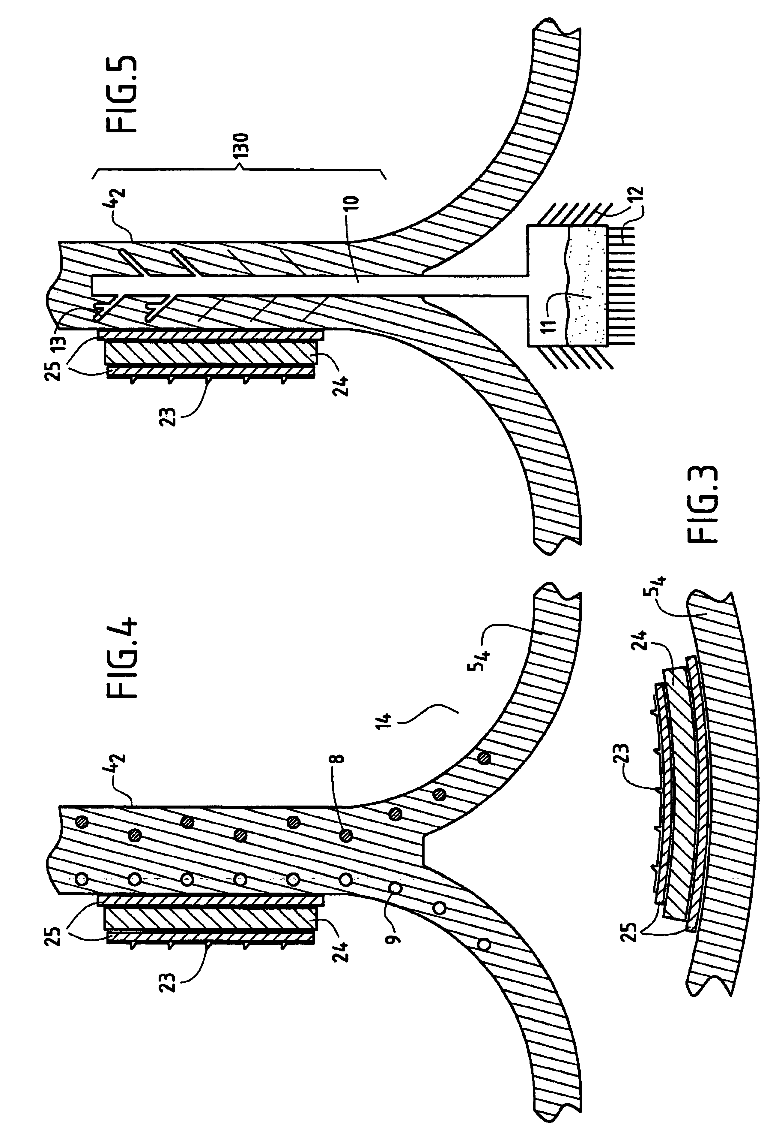
Heat flows through the insulation
system of the tank have the effect of cooling the concrete, and this cooling is limited only by supplying heat taken either from the bottom portion of the concrete
hull of the barge which is in contact with sea water, or from the top portion which is in contact with
ambient air, or else by adding additional heat directly within the
mass of the concrete.
It is imperative to limit the extent to which the concrete is cooled since below a certain temperature the steel reinforcement becomes fragile and the strength of the structure is reduced very significantly.

