A Wind Turbine Blade Having Deployable Aerodynamic Devices

a technology aerodynamic devices, which is applied in the direction of wind turbines, engine components, wind turbines, etc., can solve the problems of increased operational noise increased drag effect of wind turbine blades, and flow separation, and achieve the effect of preventing flow separation

Active Publication Date: 2016-10-27
LM WP PATENT HLDG
View PDF8 Cites 21 Cited by
  • Summary
  • Abstract
  • Description
  • Claims
  • Application Information

AI Technical Summary

Benefits of technology

[0008]wherein the flexing of said at least one flexible member acts to deploy at least one aerodynamic device, preferably vorte

Problems solved by technology

One issue with such devices, however, is that the bending of such devices during operation of the wind turbine may result in flow separation is the region of the devices, due to the relatively high

Method used


Image

  • A Wind Turbine Blade Having Deployable Aerodynamic Devices
  • A Wind Turbine Blade Having Deployable Aerodynamic Devices
  • A Wind Turbine Blade Having Deployable Aerodynamic Devices

Examples


Embodiment Construction

[0057]An embodiment of the invention will now be described, by way of example only, with reference to the accompanying drawings, in which:

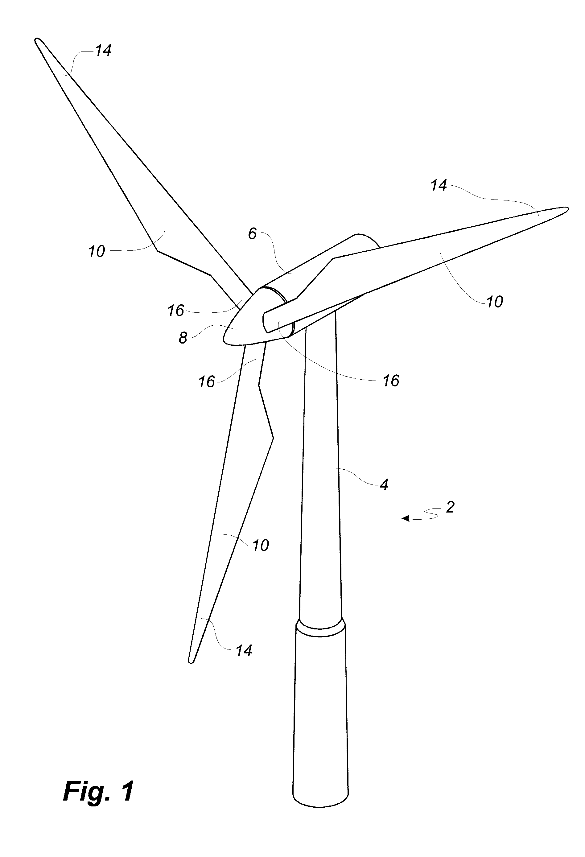
[0058]FIG. 1 shows a wind turbine;

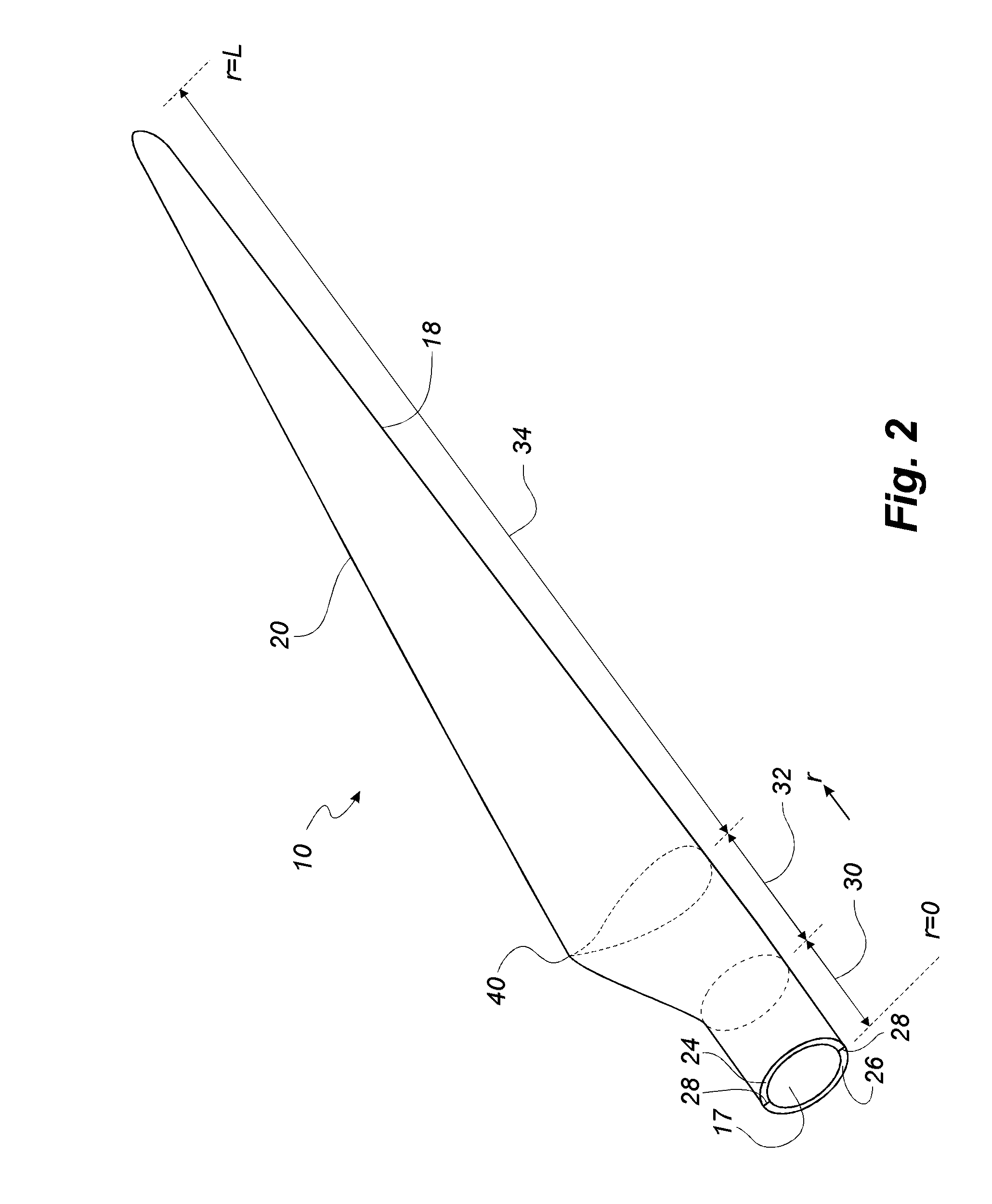
[0059]FIG. 2 shows a schematic view of a wind turbine blade according to the invention;

[0060]FIG. 3 shows a schematic view of an airfoil profile of the blade of FIG. 2;

[0061]FIG. 4 shows a schematic view of the wind turbine blade of FIG. 2, seen from above and from the side;

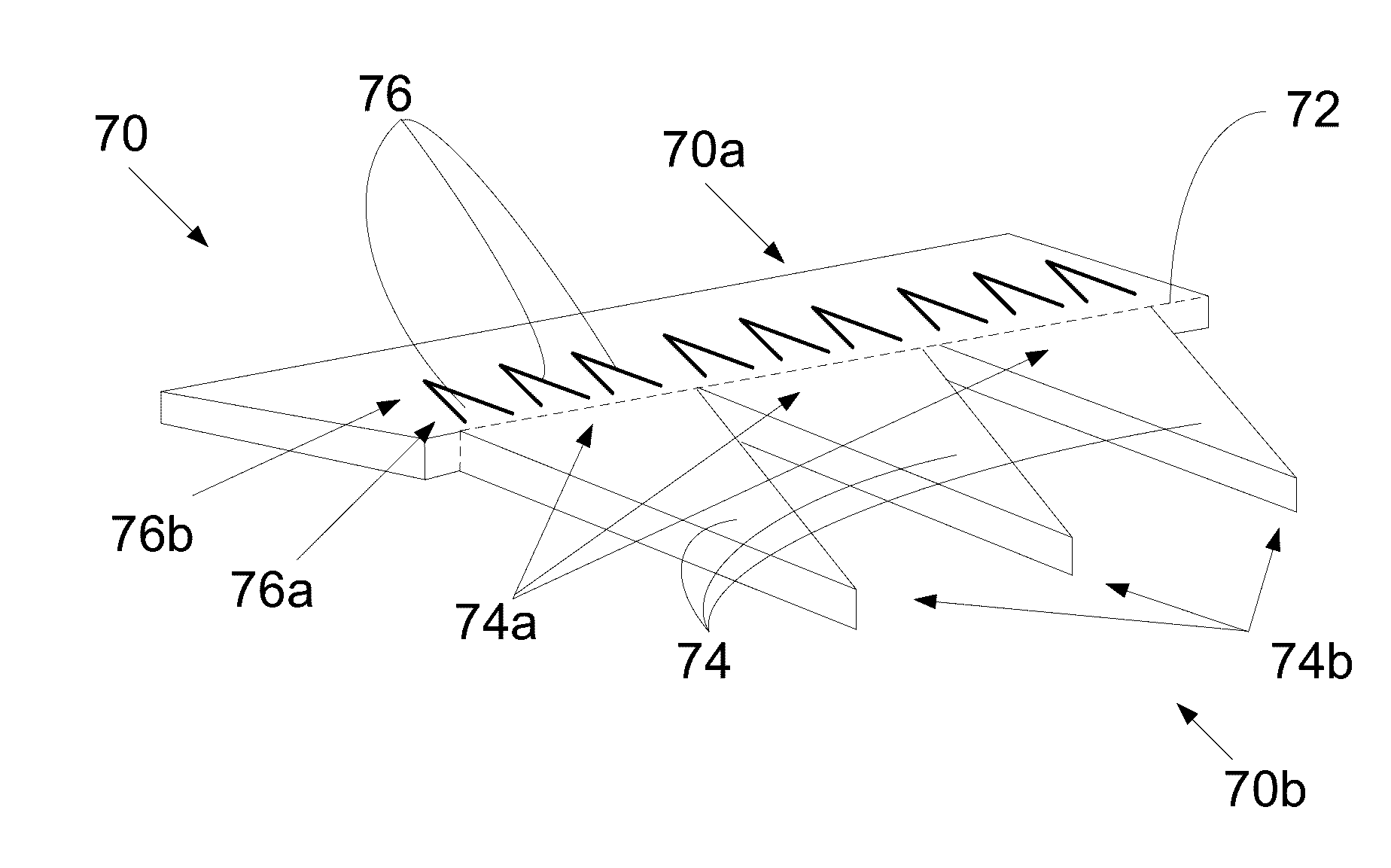
[0062]FIG. 5 illustrates a top plan view of a trailing edge plate according to an aspect of the invention;

[0063]FIG. 6 illustrates a perspective view of the trailing edge plate of FIG. 5;

[0064]FIG. 7 shows side views of the trailing edge plate of FIG. 5 before and after flexing of the plate;

[0065]FIG. 8 illustrates a top plan view of an alternative design of trailing edge plate according to the invention; and

[0066]FIG. 9 illustrates alternative constructions of the trailing edge plate of FIG. 5.

[0067]It will be understood that elements common t...


PUM


Abstract

A wind turbine blade is described, as well as a trailing edge plate for a wind turbine blade. A flexible flow modulation device, e.g. an acoustic flap or a plurality of serrations, is arranged at the trailing edge of a wind turbine blade, wherein the flexible device is coupled to at least one aerodynamic device, preferably vortex generators. As the flexible device is bent by action of flow over the wind turbine blade, the at least one aerodynamic device is deployed to provide for attached flow over the bent flexible device.

Description

FIELD OF THE INVENTION[0001]The present invention relates to a wind turbine blade having deployable aerodynamic devices, and to a trailing edge plate having deployable aerodynamic devices for attachment to the trailing edge of a wind turbine blade.BACKGROUND OF THE INVENTION[0002]In an effort to increase lift or reduce drag and / or noise levels of wind turbine blades, devices are often used at the trailing edge of wind turbine blades to adjust or regulate the flow in the wake of the wind turbine blade. Such devices may include serrations, bristles, or acoustic flaps. These devices operate through the modification of the flow properties, and / or through the adsorption of energy from the airflow over the blades through mechanical bending of the devices under action of the wind.[0003]One issue with such devices, however, is that the bending of such devices during operation of the wind turbine may result in flow separation is the region of the devices, due to the relatively high angle of ...

Claims


Application Information

Patent Timeline
IPC IPC(8): F03D1/06
CPCF03D1/0633F05B2240/2211F05B2240/311F05B2240/122Y02E10/72F05B2240/305F05B2240/3062
Inventor ARCE, CARLOSDAHL, MARTINMADSEN, JESPER
Owner LM WP PATENT HLDG
Why Eureka
Try Eureka