Pit-type compressor blade and control method for flow separation in cascade

A technology of flow separation and control method, which is applied in the direction of machines/engines, components of pumping devices for elastic fluids, mechanical equipment, etc., which can solve the problems of limited performance improvement, high cost, and difficult application of compressors, and achieve The effect of suppressing flow separation and increasing the kinetic energy level

Inactive Publication Date: 2018-12-21
大连凌海华威科技服务有限责任公司
View PDF8 Cites 9 Cited by
  • Summary
  • Abstract
  • Description
  • Claims
  • Application Information

AI Technical Summary

Problems solved by technology

Active flow control techniques (such as boundary layer suction, excitation and air blowing, etc.) are difficult to apply, additional accessories are added, and the cost is high
However, the existing passive control technology (such as blade sweep, end wall wing knife, etc.) has poor adaptability under variable working conditions.
Moreover, the passive flow control technology can only improve the performance of the compressor to a limited extent, which can no longer meet the demand for continuous improvement of the performance of the compressor.

Method used


Image

  • Pit-type compressor blade and control method for flow separation in cascade
  • Pit-type compressor blade and control method for flow separation in cascade
  • Pit-type compressor blade and control method for flow separation in cascade

Examples


Embodiment 1

[0039] On the one hand, the technical solution proposed by the present invention is a dimpled compressor blade, and dimples are arranged on the compressor blade.

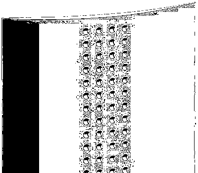
[0040] Further, the shape of the crater includes a flow-direction long-axis ellipsoid, a span-direction long-axis ellipsoid, and a crescent crater.

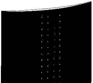
[0041] Further, the arrangement of the pits includes full leaf height parallel lattice, full leaf height staggered lattice, middle leaf span lattice, proximal wall lattice, and free lattice.

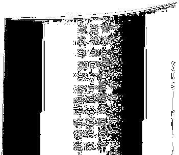
[0042] Further, the dimples are arranged in multiple rows of equally spaced dimples within a certain chord length position on the suction surface of the compressor blade, and the chord length position includes the leading edge, blade center or trailing edge.

[0043] On the other hand, the present invention proposes a method for controlling flow separation in the cascade by dimpled compressor blades. Dimples are used as a vortex generator, and when the fluid in the boundary layer...


PUM


Abstract

The invention relates to the technical field of turbomachines, in particular to a pit-type compressor blade and a control method for flow separation in a cascade, wherein the compressor blade is provided with a pit. The pit is used as a kind of vortex generator, when the boundary layer fluid flows through the suction surface of the blade, a different form of vortex structure will be formed inside,and the generated vortex will promote the mixing of low-energy and high-entropy fluid and extra-layer fluid in the boundary layer, thereby increasing the kinetic energy level of the boundary layer and suppressing the flow separation, it is mainly used to control the flow separation in a stationary cascade of a compressor and reduce the flow loss, thereby improving the flow condition and the aerodynamic performance of the stationary cascade of the compressor.

Description

technical field [0001] The invention relates to the technical field of turbomachinery, in particular to a dimpled compressor blade and a control method for flow separation in the blade cascade. Background technique [0002] Compressor: A component in a gas turbine engine that uses high-speed rotating blades to do work on the air to increase the air pressure. The axial flow compressor is composed of multi-stage moving and stationary blades arranged in a staggered manner. [0003] The compressor is a key component of aviation and ground gas turbine engines, which can add power and boost to the gas, and its performance determines the performance and reliability of the entire engine. However, due to the combination of adverse pressure gradient and gas viscosity, the internal fluid will separate. The accumulation of low-energy fluid due to separation will block the flow channel, reduce the diffuser capacity of the compressor, and induce unstable working conditions of the compre...

Claims


Application Information

Patent Timeline
Patent Type & Authority Applications(China)
IPC IPC(8): F04D29/54F04D29/66
CPCF04D29/544F04D29/667
Inventor 陆华伟郭爽杨益王宇王龙庞文瑄
Owner 大连凌海华威科技服务有限责任公司
Why Eureka
Try Eureka