Exhaust steam cylinder of miniature steam turbine

A steam exhaust cylinder and steam turbine technology, which is applied in the field of steam turbine equipment, can solve the problems of reduced working capacity of the final stage, reduced enthalpy drop of the final stage, and increased pressure, so as to reduce the influence of flow stability and eliminate the influence of steam pressure , The effect of eliminating the influence of work ability

Active Publication Date: 2012-05-02
QINGDAO JIENENG STEAM TURBINE GROUP CO LTD
View PDF6 Cites 9 Cited by
  • Summary
  • Abstract
  • Description
  • Claims
  • Application Information

AI Technical Summary

Problems solved by technology

[0004] First of all, under the condition of given condenser vacuum degree, reducing the static pressure at the outlet section of the cascade of the steam turbine can increase the available enthalpy drop of the steam turbine and increase the output power of the steam turbine. However, in the existing exhaust cylinders, each The inner wall angle is right-angled, and the reversal of the steam flow from the axial direction of the exhaust cylinder to the radial direction of the exhaust cylinder will cause a large pressure gradient in the radial and circumferential directions of the upper and lower parts of the exhaust cylinder. There will be a strong vortex secondary flow, and the vortex secondary flow will increase the pressure in the nearby area, and further affect the outlet of the final cascade, so that the steam pressure at the outlet of the final cascade will increase, resulting in the final enthalpy The drop is reduced, which weakens the working ability of the steam turbine
[0005] Secondly, the outlet pressure of the exhaust cylinder is determined, and the existing exhaust cylinder is equipped with reinforcing ribs 101 and reinforcing columns 201 uniformly arranged in the circumferential direction, and the steam pressure at the side of the reinforcing ribs 101 and reinforcing columns 201 facing the direction of steam flow When the steam pressure increases, the steam pressure at the other side decreases. When the steam passes through the above-ment...

Method used


Image

  • Exhaust steam cylinder of miniature steam turbine
  • Exhaust steam cylinder of miniature steam turbine
  • Exhaust steam cylinder of miniature steam turbine

Examples


Embodiment Construction

[0034] The following will clearly and completely describe the technical solutions in the embodiments of the present invention with reference to the accompanying drawings in the embodiments of the present invention. Obviously, the described embodiments are only some, not all, embodiments of the present invention. Based on the embodiments of the present invention, all other embodiments obtained by persons of ordinary skill in the art without making creative efforts belong to the protection scope of the present invention.

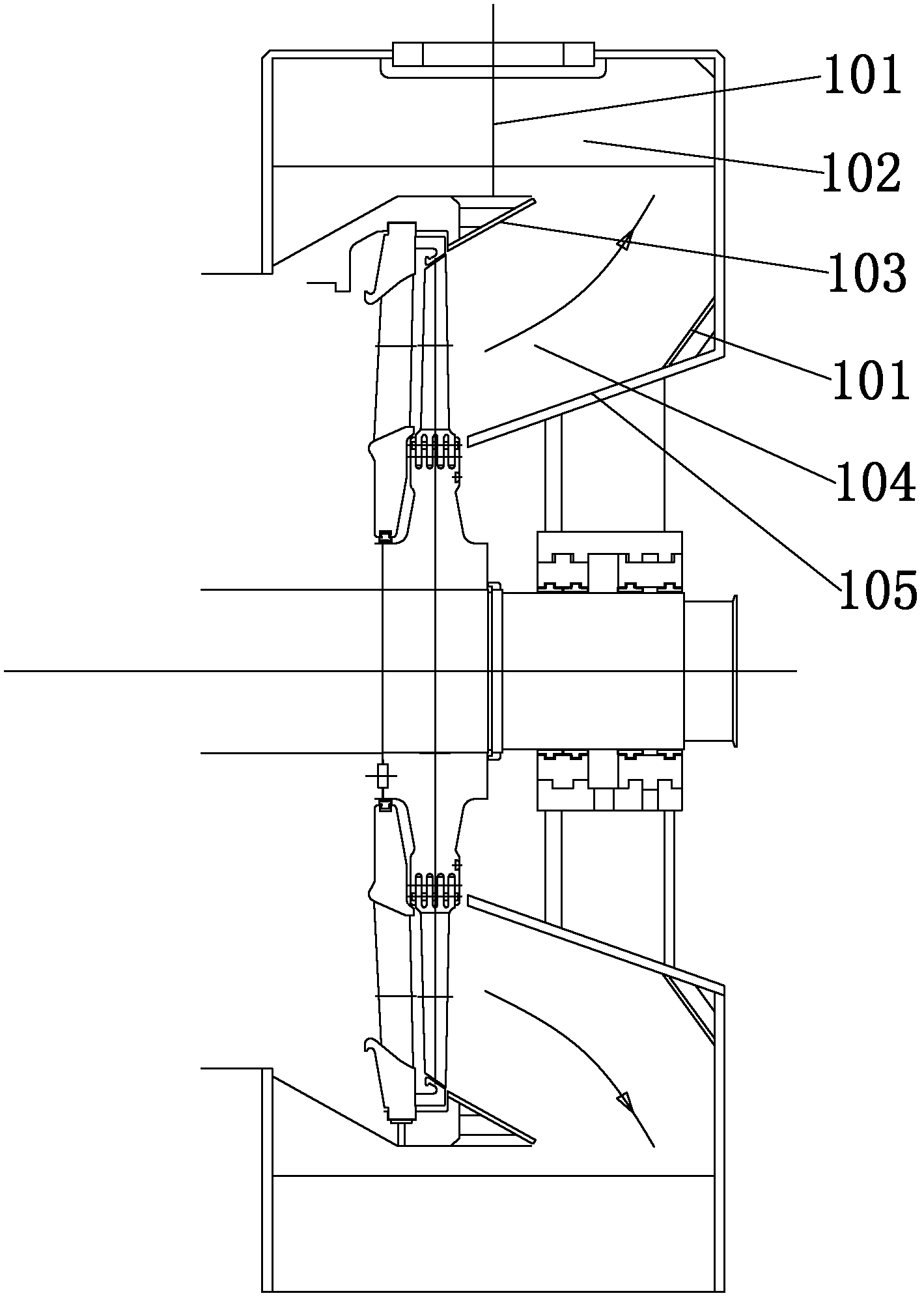
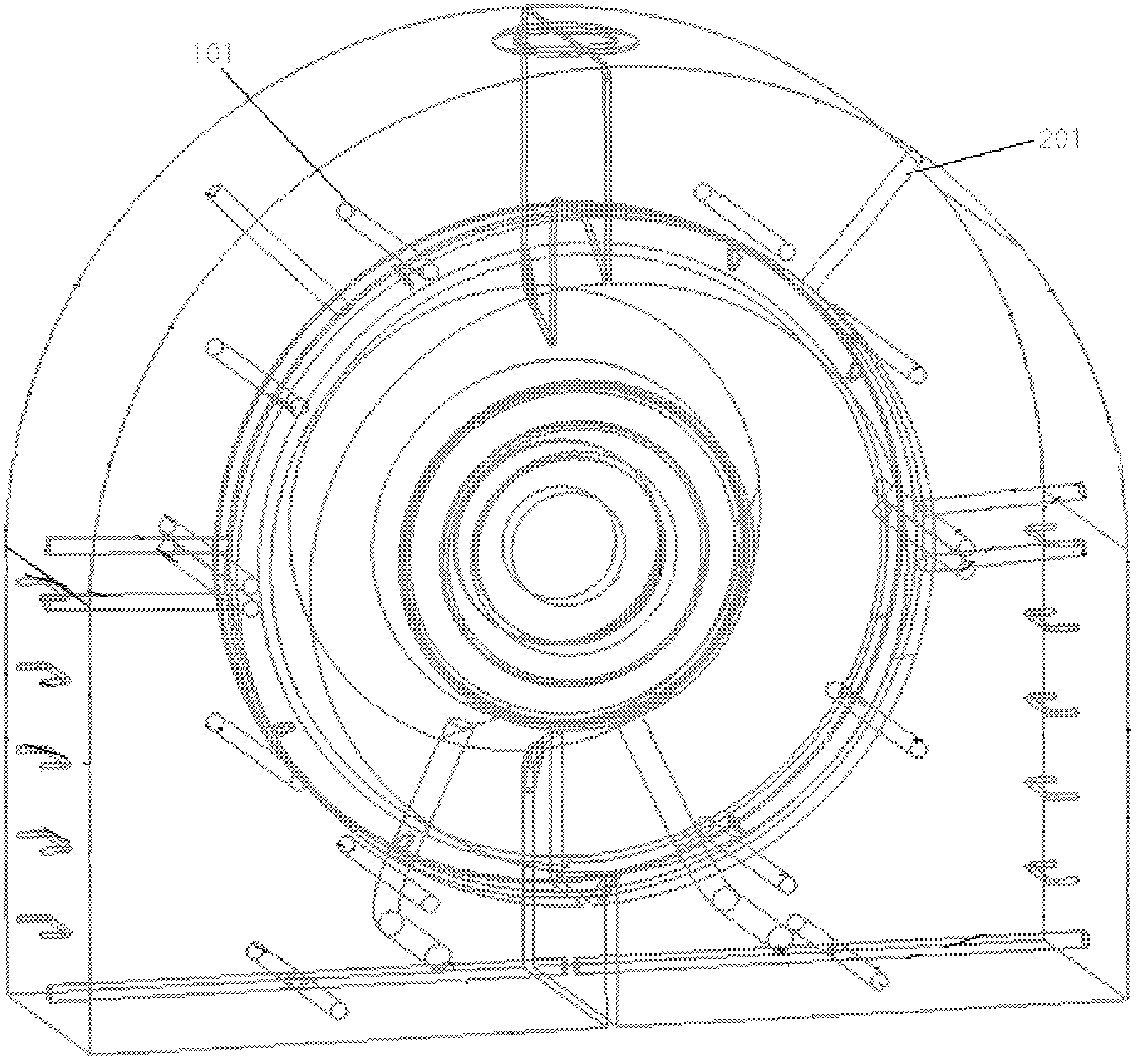
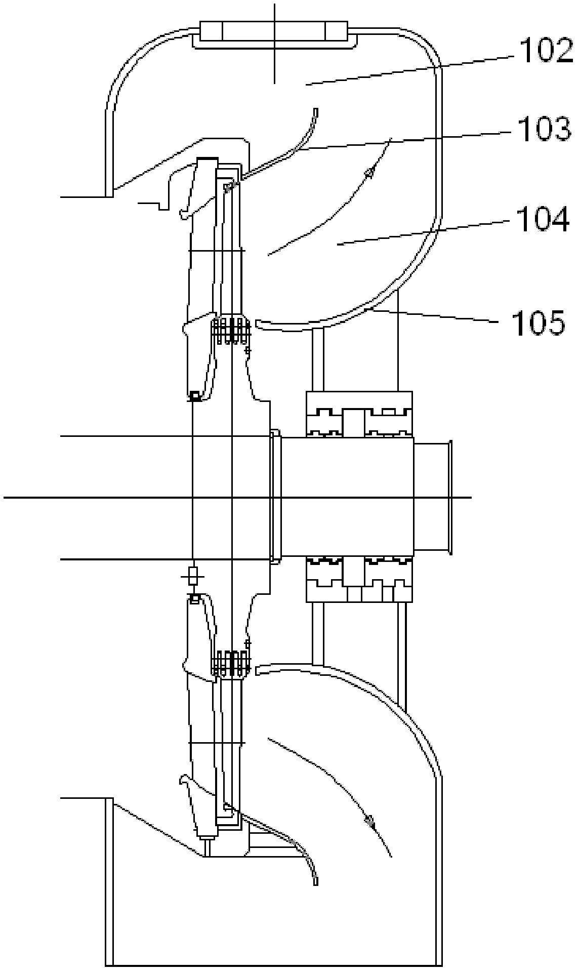
[0035] The embodiment of the invention discloses a steam exhaust cylinder of a small steam turbine, which can prevent the occurrence of vortex secondary flow at the corner of the right-angled inner wall, and eliminate the influence of the vortex secondary flow on the steam pressure at the outlet of the last-stage cascade of the steam turbine.

[0036] see Figure 3-Figure 4, the exhaust cylinder of the small steam turbine provided by the embodiment of the pres...


PUM


Abstract

The invention discloses an exhaust steam cylinder of a miniature steam turbine, which comprises a volute and a diffuser, wherein the diffuser comprises an inner deflector and an outer deflector; the volute is arranged on the circumference of the diffuser and comprises an upper wall and a side wall; the width of the volute along the axial direction of the exhaust steam cylinder is bigger than that of the diffuser; the outer deflector is connected with the side wall, and the inner deflector is arranged in the volute; inner wall corners at the connecting part of the upper wall and the side wall and the connecting part of the outer deflector and the side wall are both arc-shaped wall corners; the side face of the inner deflector is a side face consisting of first non-uniform rational spline curves; and the side face of the inner deflector consists of second non-uniform rational spline curves. The exhaust steam cylinder of the miniature steam turbine, provided by the invention, can prevent vortex secondary flow from occurring at the wall corners and eliminate the influence of the vortex secondary flow on steam pressure at the final blade cascade outlet of the miniature steam turbine.

Description

technical field [0001] The invention relates to the technical field of steam turbine equipment, in particular to a steam exhaust cylinder of a small steam turbine. Background technique [0002] The exhaust cylinder of the steam turbine is the channel connecting the outlet of the final stage cascade of the condensing steam turbine and the condenser. The exhaust steam from the cascade is directed into the condenser. [0003] see Figure 1-Figure 2 , the existing small steam turbine exhaust cylinder includes a diffuser 104 and a volute 102, wherein the diffuser 104 includes an inner deflector 103 and an outer deflector 105; the volute 102 includes an upper wall and a side wall; the volute 102 It is arranged on the outer periphery of the above-mentioned diffuser 104, and its width along the axial direction of the exhaust cylinder is larger than the width of the above-mentioned diffuser 104; the above-mentioned outer deflector 105 is connected with the above-mentioned side wall,...

Claims


Application Information

Patent Timeline
IPC IPC(8): F01D25/30
Inventor 潘世明姚宏张佩娟
Owner QINGDAO JIENENG STEAM TURBINE GROUP CO LTD
Why Eureka
Try Eureka