

Gas compressor stationary blade cascade with equal-width linear groove formed in blade root
A technology for compressors and sub-leaf cascades, which is applied in passive flow control, a flow control scheme for the blade root of a compressor stator cascade, and the flow control field of a compressor stator cascade, which can solve the slotting scheme to connect the arcs randomly and control the The solution is difficult to optimize the design, lack of design guidelines and other problems, to achieve the effect of convenient optimization design, good engineering application prospects, and easy processing
- Summary
- Abstract
- Description
- Claims
- Application Information
AI Technical Summary
Problems solved by technology
Method used
Image

Examples
Embodiment Construction
[0024] Specific embodiments of the present invention will be described below in conjunction with the accompanying drawings.
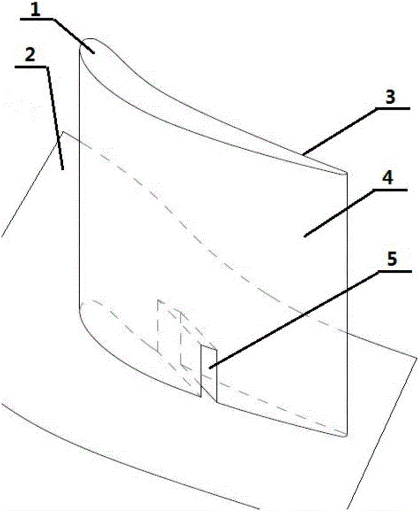
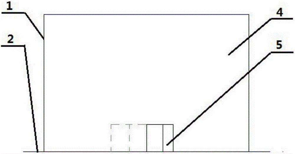
[0025] Such as figure 1 As shown, the compressor stator cascade with equal-width linear grooves on the blade root has equal-width linear grooves 5 on the end wall 2 of the root of the cascade 1 from the pressure surface 3 to the suction surface 4 of the cascade 1 .
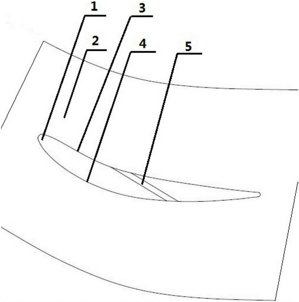
[0026] Such as figure 2 As shown, according to the PVD prototype stator cascade flow field, the position of the outlet of the channel 5 on the suction surface 4 is selected before the separation point; along the axial direction of the cascade, the position of the inlet of the channel 5 on the pressure surface 3 is located on the suction surface 4 Upstream of the outlet position; according to the pressure distribution on the surface of the PVD prototype stator cascade, the position of the inlet of the channel 5 on the pressure surface 3 is selected at the place where the static pressure on...
PUM
 Abstract
Description
Claims
Application Information