Cooled turbine guide vane or blade for a turbomachine

a technology of turbine guide vane and turbine blade, which is applied in the direction of engine fuction, stators, machines/engines, etc., can solve the problem of limited maximum acceptable inlet temperature, increase the heat transfer of convective cooling by cooling fluid flowing through the cavity, and reduce the amount of cooling fluid

Inactive Publication Date: 2018-02-20
SIEMENS ENERGY GLOBAL GMBH & CO KG
View PDF25 Cites 11 Cited by
  • Summary
  • Abstract
  • Description
  • Claims
  • Application Information

AI Technical Summary

Benefits of technology

[0007]The inventive turbine airfoil, particularly a blade or a vane for a turbomachine, comprises a suction side wall and a pressure side wall bordering an airfoil cavity, which is adapted to be flowed through by a cooling fluid for cooling of the side walls and therefore of the turbine airfoil, wherein the suction side wall comprises at least one protrusion extending therefrom inside the cavity, characterized in that the number of the at least one protrusion on the suction side wall is higher than the number of protrusions on the pressure side wall, the density of the at least one protrusion on the suction side wall is higher than the density of protrusions on the pressure side wall and / or the surface of the at least one protrusion on the suction side wall is larger than the surface of protrusions on the pressure side wall, so that the heat transfer from the suction side wall to the cooling fluid is higher compared to the heat transfer from the pressure side wall to the cooling fluid during the operation of the turbomachine such that an excess of the heat transfer from the suction side wall is generated.
[0009]The inventive turbine airfoil or turbine blading can be a rotating blade or a stationary guide vane. The inventive turbine blading comprises one protrusion or a plurality of protrusions. During operation of the turbomachine, the walls of the turbine blade or guide vane are heated up due to hot gas flowing along the external walls. Heat is transported by heat conduction to the protrusion of the suction side wall. The protrusion has the effect of increasing the inner surface of the suction side wall, whereby convective cooling by the cooling fluid flowing through the cavity is increased. The cooling may particularly be film cooling and / or convective cooling. The overall cooling of the suction side wall comprises a contribution from the convective cooling from inside the turbine airfoil and may have an additional contribution from the film cooling from outside the blade or guide vane. Because of the increased heat transfer of the convective cooling, a reduced amount of the cooling fluid overall for the blading or specifically for the external film cooling can be used for the suction side wall. Along the suction side wall the velocity of hot gas during the operation of the turbomachine is higher compared to that of the pressure side wall. Therefore, mixing losses in areas with high velocity gradients between the hot gas and the cooling fluid are reduced and consequently the efficiency of the turbomachine is advantageously increased. The extension of the protrusion should be specified such that a compromise is found between the large inner surface for an effective cooling and a small blockage for the cooling fluid flow inside the cavity.
[0010]It is preferred that at least one of the protrusions is a turbulator for the cooling fluid flow. Downstream from the turbulator a turbulent boundary layer is developing, which advantageously cools the suction side wall efficiently by the convective cooling. At least one of the protrusions is preferably a cylinder, a cone, a pyramid or a tetrahedron. Alternatively, at least one of the protrusions is preferably an elongated rib, in particular with a triangular cross section. The elongated rib can advantageously increase the mechanical stability of the turbine blading. It is preferred that on the downstream side of the protrusion a flow separation, which would lead to a formation of a recirculation zone, is prevented. The cooling fluid can be trapped in the recirculation zone, whereby the convective cooling would be affected. With the preferred shapes of the protrusion a large surface inside the turbine airfoil with a small blockage for the cooling fluid flow can advantageously be achieved.
[0011]It is preferred that at least one of the protrusions extends from the suction side wall to the pressure side wall. The turbine airfoil has consequently a high mechanical stability. In order to obtain the higher heat transfer from the suction side wall to the cooling fluid compared to that of the pressure side wall, the thickness of the protrusion portion attached to the suction side wall is preferably larger than the thickness of the protrusion portion attached to the pressure side wall. At least one of the protrusions is preferably a truncated cone and / or a cylinder. Further, it is preferred that at least one of the protrusions is located adjacent to the trailing edge of the turbine blade or guide vane. Cooling is in particular important near the trailing edge and the protrusion adjacent to the trailing edge increases advantageously the convective cooling in this area. Further, it is preferred that the turbine blade or vane comprises at least one passage in the trailing edge connecting the cavity with the outside of the blade or vane, wherein the passage is provided for the outflow of the cooling fluid from the cavity. Therefore, the flow of the cooling fluid around the protrusion adjacent to the trailing edge is high and the convective cooling of this protrusion is advantageously high.
[0012]In an embodiment the suction side wall comprises a plurality of film cooling holes. Via the film cooling holes the cooling fluid is transported from the cavity to the surface of the blade or vane in order to form a cooling film on the turbine blade or vane surface, i.e. the outside surface of the airfoil along which the hot gas will pass during operation. Hence, the suction side wall can advantageously be cooled both from inside and outside of the blade or vane, i.e. the airfoil or the blading. The cooling film not only cools the airfoil by convection but it also functions as a barrier against the hot gas to prevent the hot gas from flowing at the turbine airfoil wall. The number of the film cooling holes on the suction side wall is smaller than the number of film cooling holes on the pressure side wall, the density of the film cooling holes on the suction side wall is smaller than the density of film cooling holes on the pressure side wall and / or the diameter of the film cooling holes on the suction side wall is smaller than the diameter of film cooling holes on the pressure side wall so that the excess of the heat transfer caused by the protrusions is compensated. Therefore, the amount of cooling fluid transported on the turbine airfoil surface of the suction side wall is minimised. Consequently, the mixing losses of the cooling fluid and the hot gas are advantageously lower while the heat transfer from the suction side wall to the cooling fluid is unchanged.
[0013]It is also possible that the turbine blade or vane comprises on its outer surface a thermal barrier coating, e.g. a ceramic coating, to increase the thermal resilience of the turbine blading and therefore increase the lifetime of the turbine blading.

Problems solved by technology

The maximal acceptable inlet temperature is limited because of the limited thermal resilience of the turbine blading.

Method used


Image

  • Cooled turbine guide vane or blade for a turbomachine
  • Cooled turbine guide vane or blade for a turbomachine

Examples


Embodiment Construction

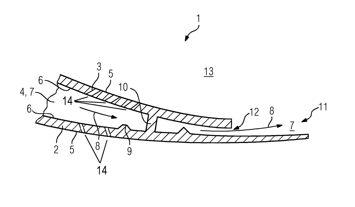
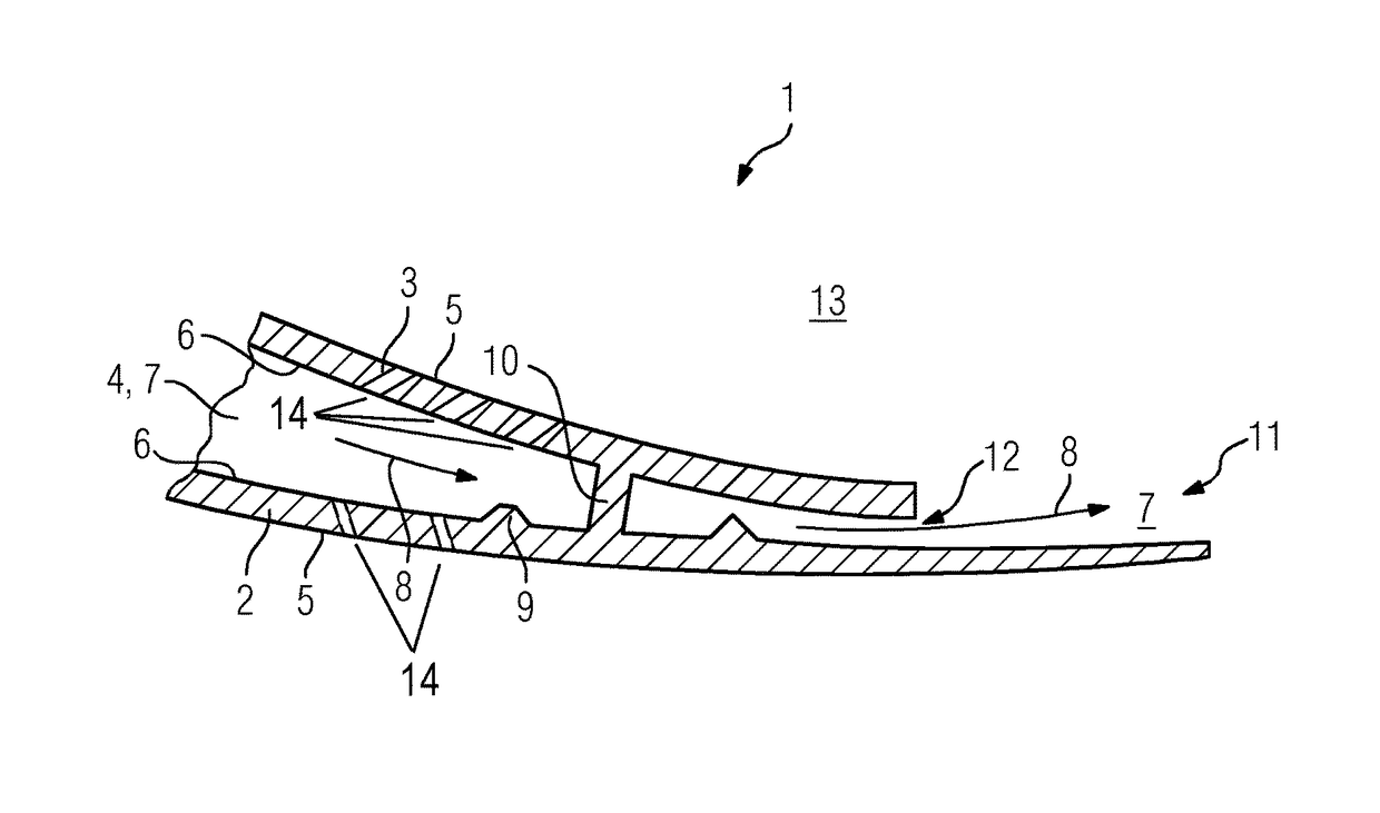
[0015]In the FIGURE, an embodiment of a turbine airfoil 1 of a turbomachine is shown. The turbine airfoil 1 can be a rotor blade as well as a guide vane. The turbine airfoil 1 comprises a suction side wall 2 and a pressure side wall 3 which border a cavity 4—an airfoil cavity, a hollow space inside the airfoil 1—inside the turbine airfoil 1. In the FIGURE, the trailing edge 11 of the turbine airfoil 1 and the area adjacent to the trailing edge 11 are shown. The width of the cavity 4 reduces towards the trailing edge 11.

[0016]Each of the walls 2, 3 comprises an inner face 6 and an outer face 5. During the operation of the turbomachine a hot gas (not shown) flows in the flow channel 13 between two adjacent turbine airfoils along the walls 2, 3 with a main flow direction directed from the leading edge (not shown) to the trailing edge 11. In the cavity a cooling fluid 7 flows with a cooling fluid main flow direction 8 which is substantially parallel to the walls 2, 3 and oriented toward...


PUM


Abstract

A turbine airfoil has a suction side wall and a pressure side wall of an airfoil cavity, through which a cooling fluid flows for cooling of the side walls. The suction side wall has one or more protrusions extending therefrom into the airfoil cavity. The protrusions are arranged such that: a number of the one or more protrusions on the suction side wall is higher than a number of protrusions on the pressure side wall; and / or a protrusion density on the suction side wall is higher than a protrusion density on the pressure side wall, and / or a total protrusion surface area on the suction side wall is larger than a total protrusion surface area on the pressure side wall, so that the heat transfer from the suction side wall to the cooling fluid is higher compared to that of the pressure side wall during operation of the turbomachine.

Description

CROSS REFERENCE TO RELATED APPLICATIONS[0001]This application is the US National Stage of International Application No. PCT / EP2012 / 069396 filed Oct. 2, 2012, and claims the benefit thereof. The International Application claims the benefit of European Application No. EP 11185955 filed Oct. 20, 2011. All of the applications are incorporated by reference herein in their entirety.FIELD OF INVENTION[0002]The invention relates to a cooled blading of a turbine.BACKGROUND OF INVENTION[0003]A turbomachine, in particular a gas turbine, comprises a turbine in which a hot gas is expanded for attaining a mechanical work, after the hot gas had been compressed in a compressor and heated up in a combustion chamber. For a high mass flow rate and therefore for a high power of the gas turbine the latter is designed as an axial gas turbine, wherein the turbine comprises a plurality of consecutive blade rings. The blade rings comprise alternately guide vanes attached to the housing of the gas turbine an...

Claims


Application Information

Patent Timeline
Patent Type & Authority Patents(United States)
IPC IPC(8): F01D5/18F01D9/06
CPCF01D5/187F01D9/065F01D5/186F05D2260/203
Inventor SHEPHERD, ANDREW
Owner SIEMENS ENERGY GLOBAL GMBH & CO KG
Why Eureka
Try Eureka