Pit type intermediate case for restraining flow separation

A flow separation and intermediary technology, applied in the direction of fluid flow, mechanical equipment, etc., to achieve the effect of improving aerodynamic performance, increasing kinetic energy level, and reducing flow loss

Active Publication Date: 2021-11-02
DALIAN MARITIME UNIVERSITY
View PDF6 Cites 0 Cited by
  • Summary
  • Abstract
  • Description
  • Claims
  • Application Information

AI Technical Summary

Problems solved by technology

Since active flow control is severely restricted by external conditions, the application has certain limitations.

Method used


Image

  • Pit type intermediate case for restraining flow separation
  • Pit type intermediate case for restraining flow separation
  • Pit type intermediate case for restraining flow separation

Examples


Embodiment Construction

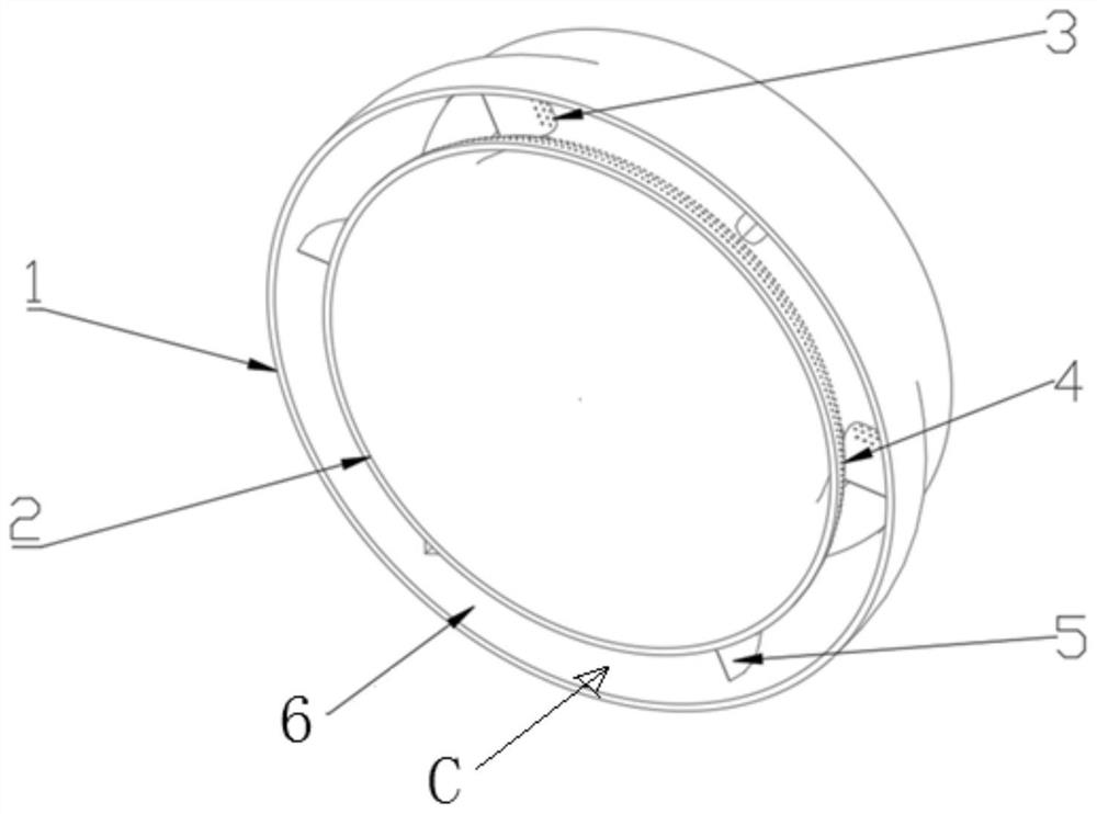
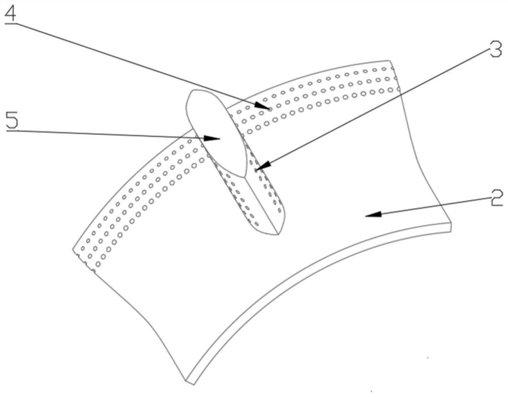
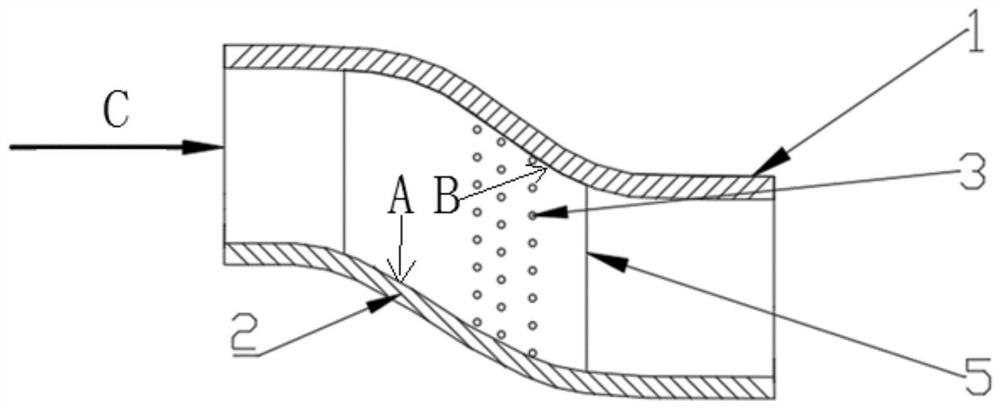
[0019] like figure 1 , figure 2 and image 3 Shown is the pit-type intermediate casing for suppressing flow separation disclosed in the present invention, comprising an intermediate casing outer ring 1, an intermediate casing inner ring 2 and a plurality of support plates 5;

[0020] The intermediate casing inner ring 2 is placed in the intermediate casing outer ring 1 , and a flow annular channel 6 is formed between the intermediate casing inner ring 2 and the intermediate casing outer ring 1 . The plates 5 are evenly distributed in the flow annular channel 6 in the circumferential direction, and one end is connected with the outer wall of the intermediate casing inner ring 2, and the other end is connected with the inner wall of the intermediate casing outer ring 1. The back arc of the flow annular channel 6 and / Or the support plate 5 is further provided with a dimple for generating a vortex when the fluid flows.

[0021] Specifically, in this embodiment, both the back ...


PUM


Abstract

The invention discloses a pit type intermediate case for restraining flow separation. The pit type intermediate case comprises an intermediate case outer ring, an intermediate case inner ring and a plurality of supporting plates, wherein the intermediate case inner ring is arranged in the intermediate case outer ring, and a flowing annular channel is formed between the intermediate case inner ring and the intermediate case outer ring; the supporting plates are evenly distributed in the flowing annular channel in the circumferential direction, one ends of the supporting plates are connected with the outer wall of the intermediate case inner ring, and the other ends of the supporting plates are connected with the inner wall of the intermediate case outer ring; and pits used for generating vortexes when fluid flows through are formed in the back arc of the flowing annular channel and/or the supporting plates. Due to the fact that the pits are formed in the intermediate case, mixing of low-energy high-entropy fluid in a boundary layer and fluid outside the layer can be promoted, the kinetic energy level of the boundary layer is improved, the flow separation is restrained, flow loss is reduced, the flow condition in the intermediate case is improved, and the aerodynamic performance of the intermediate case is improved.

Description

technical field [0001] The invention relates to the technical field of fluid machinery, in particular to a pit-type intermediate casing for suppressing flow separation. Background technique [0002] In today's society, fluid machinery is increasingly playing an increasingly important role in the field of national defense science and technology. It is an important component in aviation, aerospace, navigation, energy, chemical and other fields. The main components of the fluid machinery are connected by a transition section (intermediate casing), which guides the air flow from the upstream element to the downstream element, ensuring the continuity of the flow field between the elements, and the flow annular channel of the transition section is evenly distributed in the circumferential direction. The support plate can play a supporting role. However, the large radial offset of the transition section and the support plate lead to internal flow turbulence, air flow separation, a...

Claims


Application Information

Patent Timeline
Patent Type & Authority Applications(China)
IPC IPC(8): F15D1/00
CPCF15D1/003F15D1/009
Inventor 辛建池王龙刘向阳
Owner DALIAN MARITIME UNIVERSITY
Why Eureka
Try Eureka