Vortex box, waste gas collection method and waste gas collection and disposal device

A disposal device and waste gas collection technology, which is applied to components, separation methods, chemical instruments and methods of elastic fluid pumping devices, etc., can solve the problems of low collection efficiency and high energy consumption of waste gas collection, and achieve reduced turbulence, The effect of reducing energy cost and improving efficiency

Active Publication Date: 2021-11-30
惠泽(南京)环保科技有限公司
View PDF9 Cites 0 Cited by
  • Summary
  • Abstract
  • Description
  • Claims
  • Application Information

AI Technical Summary

Problems solved by technology

[0003] Based on this, it is necessary to provide a vortex box to solve the problems of high energy consumption and low collection efficiency of waste gas collection

Method used


Image

  • Vortex box, waste gas collection method and waste gas collection and disposal device
  • Vortex box, waste gas collection method and waste gas collection and disposal device
  • Vortex box, waste gas collection method and waste gas collection and disposal device

Examples


Embodiment 1

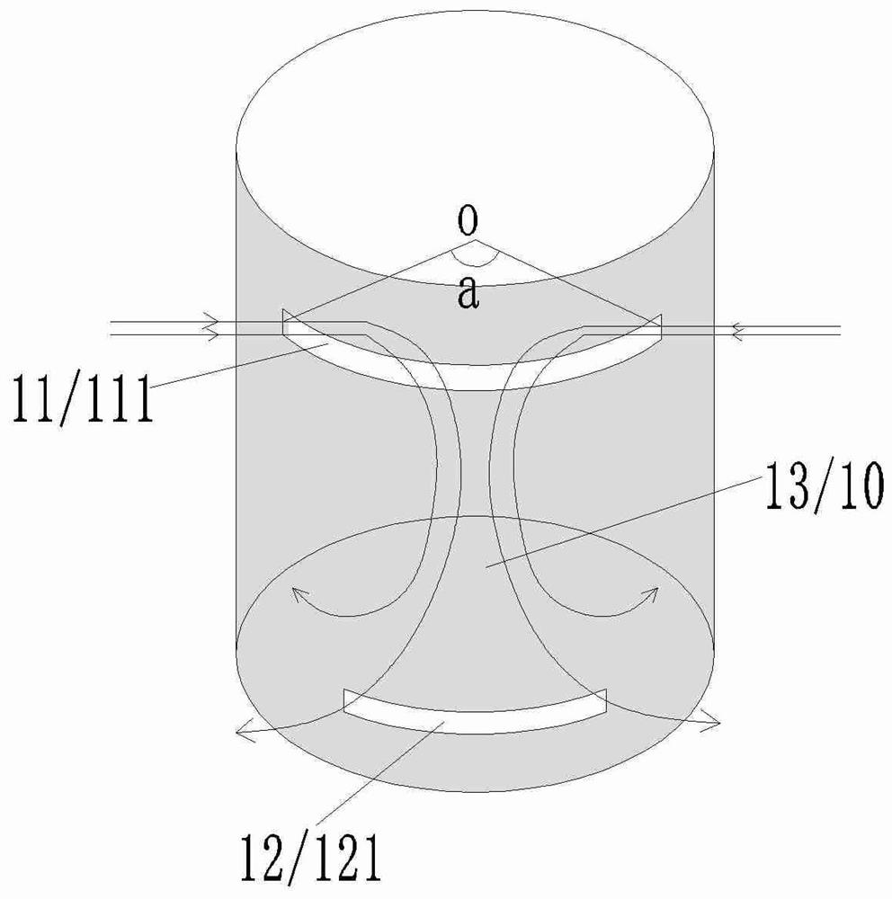
[0142] This embodiment provides a swirl box 1, please refer to figure 1 The vortex box 1 is provided with a cylindrical vortex chamber 10, and the upper side of the vortex chamber 10 is provided with an air intake assembly 11 and an air outlet assembly 12. The air intake assembly 11 only includes a first air inlet 111, and the air outlet assembly 12 is arranged on Directly below the air inlet assembly 11, the air outlet assembly 12 only includes the first air outlet 121, and the orthographic projection of the angle formed by the two ends of the first air inlet 111 and the center point O of the vortex chamber 10 on the horizontal plane is a , in this embodiment, a is 120 degrees, and the vortex chamber 10 is used as a working space. During operation, exhaust gas will be generated in the vortex chamber 10 .

[0143] The above-mentioned vortex box 1, the intake air that enters through the first air inlet 111 can be decomposed into: the first component intake air that enters throu...

Embodiment 2

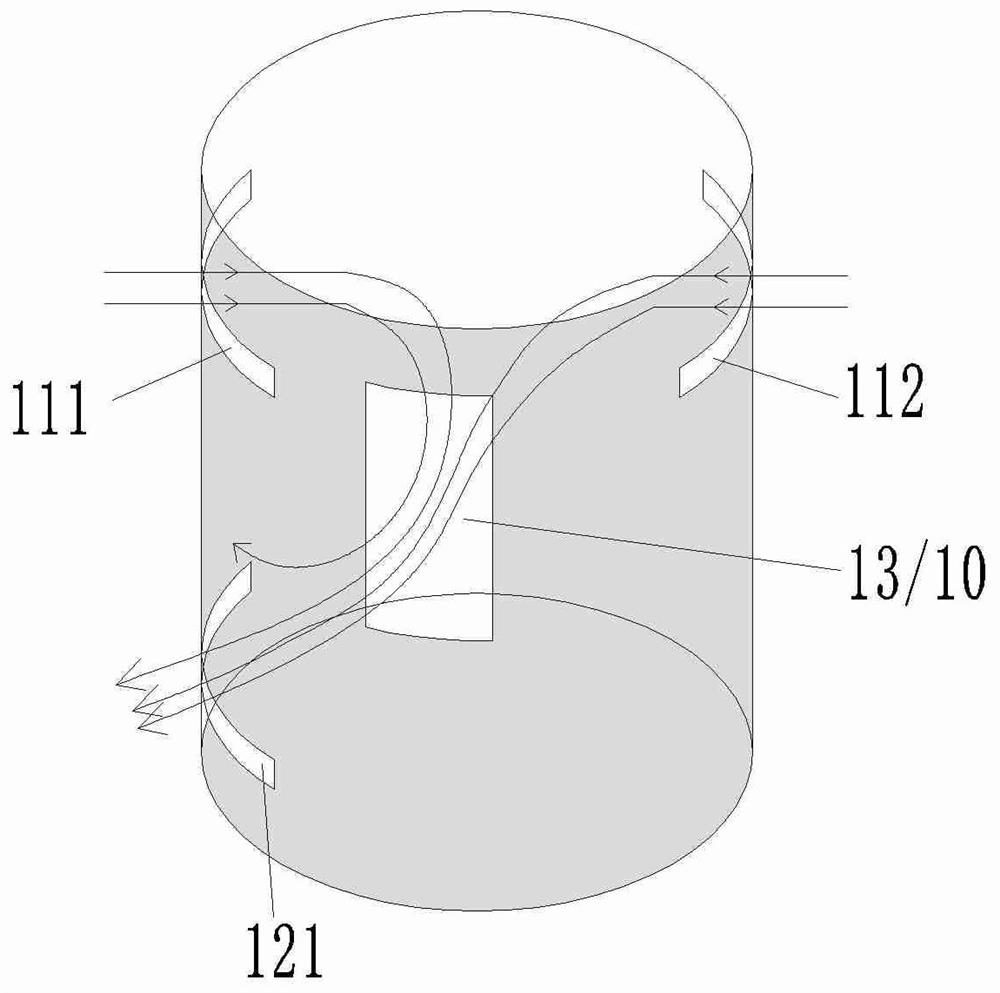
[0153] This embodiment provides a swirl box 1, please refer to figure 2 The vortex box 1 is provided with a cylindrical vortex cavity 10, the upper side of the vortex cavity 10 is provided with an air inlet combination 11, and the air intake combination 11 includes a first air inlet 111 and a second air inlet 112 arranged oppositely, The air outlet assembly 12 is arranged directly below the first air inlet 111, the air outlet assembly 12 only includes the first air outlet 121, and the waste gas channel 13 is arranged at the first air inlet 111, the second air inlet 112 and the first air outlet 121 In the triangular area between, the working space is located directly in front of the waste gas passage 13.

[0154] Above-mentioned vortex box 1, the first intake airflow that enters through the first air inlet 111 and the second intake airflow that enters through the second air inlet 112 form opposite intake airflow, the first outlet airflow that flows out through the first air ou...

Embodiment 3

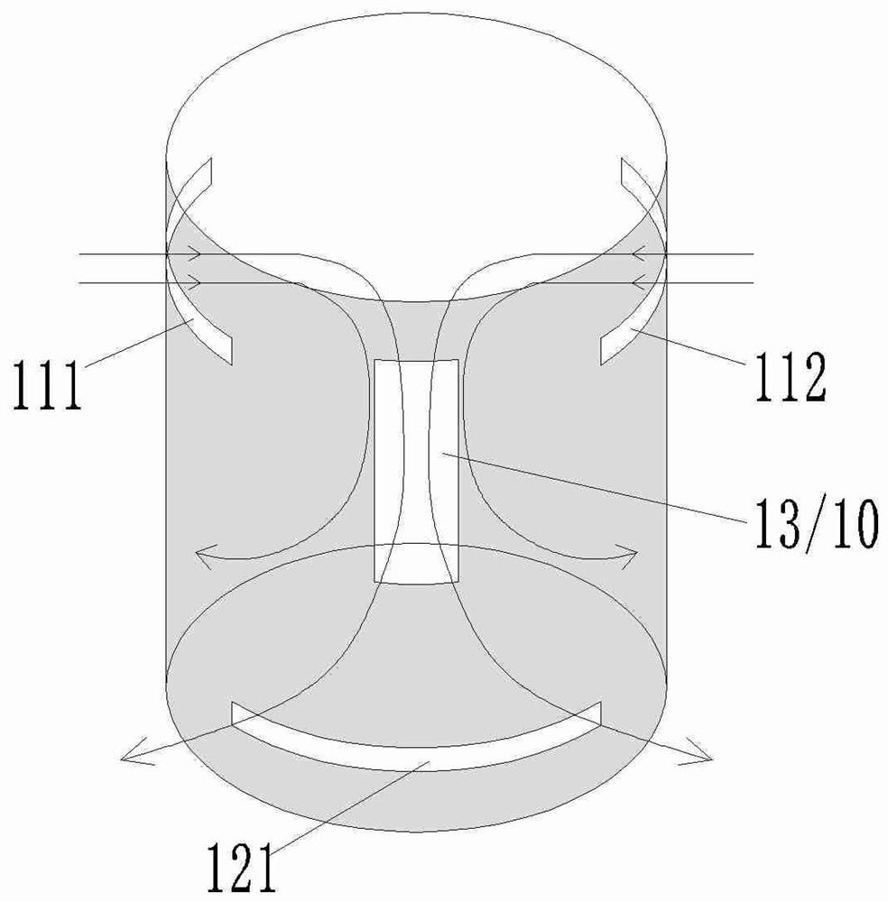
[0163] This embodiment provides a swirl box 1, please refer to image 3 The vortex box 1 is similar to the vortex box 1 provided in Embodiment 2, except that the first air outlet 121 is equidistant from the first air inlet 111 and the second air inlet 112 .

[0164] The above-mentioned vortex box 1, the first intake air that enters through the first air inlet 111 and the second intake air that enters through the second air inlet 112 constitute the opposite intake air, and the outlet air that flows out through the first air outlet 121 can be decomposed into : the first component of the airflow near the first air inlet 111 side, and the second component of the airflow near the second air inlet 112 side, the first airflow is opposite to the first component of the airflow direction, the second The direction of movement of the inlet airflow is opposite to that of the second component of the outlet airflow. When the exhaust device 3 connected to the air outlet assembly 12 was worki...


PUM


Abstract

The invention provides a vortex box, a waste gas collection method and a waste gas collection and disposal device. A vortex cavity is formed in the vortex box, a gas inlet combination and a gas outlet combination are arranged on the cavity wall of the vortex cavity, and the gas inlet combination and the gas outlet combination are spaced by a preset distance. During operation, the gas inlet flow through the gas inlet combination has an opposite component gas inlet flow, and the gas outlet flow through the gas outlet combination has a component gas outlet flow opposite to the component gas inlet flow. When the vortex box works, at least one vortex can be formed in the vortex box. After waste gas enters the vortex box, the waste gas is conveyed to the gas outlet combination under the action of vortex, the vortex enables the gas to flow in the vortex cavity in a quasi-laminar flow state, and mixing of the waste gas and fresh air can be effectively restrained; meanwhile, the vortex effectively improves the waste gas collection efficiency through the convection effect, and in addition, the waste gas collection energy consumption cost is reduced.

Description

technical field [0001] The invention relates to the technical field of waste gas treatment, in particular to a vortex box, a waste gas collection method, and a waste gas collection and treatment device. Background technique [0002] At present, when collecting the exhaust gas generated in the working space, the indoor exhaust gas is often collected by setting an air inlet on the opposite side of the air inlet, for example, the air inlet is set on the left side, and the air inlet is set on the right side , or the air inlet is arranged on the top, and the air outlet is arranged on the ground, and the air is convected by setting the air inlet and the air outlet relative to each other, so that the exhaust gas is collected through the air outlet. However, there is a problem with this setting method. When the air inlet and the air outlet are arranged opposite to each other, the airflow first hits the opposite side after entering the confined space from the air inlet, thereby formi...

Claims


Application Information

Patent Timeline
Patent Type & Authority Applications(China)
IPC IPC(8): F17D1/02B01D46/00F04D29/40F04D29/70
CPCF17D1/02F04D29/403F04D29/701
Inventor 王成林
Owner 惠泽(南京)环保科技有限公司
Why Eureka
Try Eureka