Data gathering system

a data gathering and data technology, applied in the field of data gathering system, can solve the problems of difficult detection and gathering of em signals, ekg signals, conductance communications, etc., and achieve the effect of less irritating the epidermis

Active Publication Date: 2015-04-21
PROTEUS DIGITAL HEALTH INC
View PDF1583 Cites 25 Cited by
  • Summary
  • Abstract
  • Description
  • Claims
  • Application Information

AI Technical Summary

Benefits of technology

[0011]A device for gathering data has first and second electrodes. The first electrode is coupled to a surface of interest, and the second electrode is coupled to “everything else” or “the air”. The first electrode is shielded from the second, and from most sources of parasitic capacitance, by a shield that is driven by an active driver that drives the shield to track, and ideally to match, the instantaneous potential of the electrode. The second electrode is likewise shielded in a similar way from most sources of parasitic capacitance. These shields likewise help to limit the extent to which RFI from the device electronics couples with either of the electrodes. In this way the sensing device achieves a markedly better signal-to-noise ratio at frequency bands of interest.

Problems solved by technology

Some electromagnetic communications, e.g., EKG signals, conductance communications, RF signals, etc., are very, very difficult to detect and gather, except with inconvenient or awkward data-gathering systems.
The source of the desired EM signal (for example a device within a live subject) may be overwhelmed or nearly overwhelmed by naturally occurring signals in the subject.
Such an IEM is necessarily extremely limited in the amount of electrical power available, and in the size of antenna available to couple the transmitter to nearby transmission media.
The patch has potential drawbacks, among them the risk of irritation to the epidermis due to the adhesive attachment, possible interference with freedom of movement, and perhaps aesthetically displeasing appearance to some eyes.
Experience shows, however, that at frequencies of interest (perhaps tens of kilohertz), the parasitic capacitances present in such a device 201 cause a loss of a large portion of any detected signal.
While this approach may indeed reduce RFI, it has the drawback of introducing still greater parasitic capacitances as between electrodes 203, 204.

Method used


Image

  • Data gathering system
  • Data gathering system

Examples


Embodiment Construction

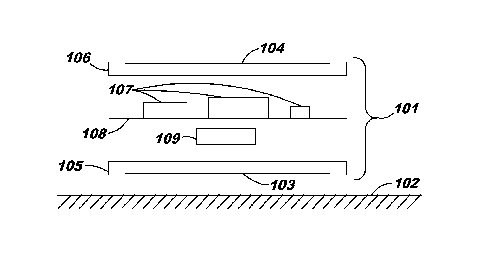
[0015]Turning to FIG. 1, what is shown is a sensing device 101 according to the invention in cross-sectional view. The sensing device has first and second electrodes 103 and 104. The first electrode 103 is coupled to a surface of interest 102, which might be tissue of a living subject, and the second electrode 104 is coupled to “everything else” or “the air”. Although it is largely a matter of semantics, one might choose to characterize the second electrode 104 as an electrode coupling to “ground” or “space ground”.

[0016]The first electrode 103 is shielded from the second electrode 104, and from most sources of parasitic capacitance, by a shield 105 that is driven by an active driver (omitted for clarity in FIG. 1) that drives the shield 105 to track, and ideally to match, the instantaneous potential of the electrode 103. The second electrode 104 is likewise shielded in a similar way from most sources of parasitic capacitance by a shield 106. These shields 105, 106 likewise help to ...


PUM


Abstract

A device for gathering data has first and second electrodes. The first electrode is coupled to a surface of interest, and the second electrode is coupled to “everything else” or “the air”. The first electrode is shielded from the second, and from most sources of parasitic capacitance, by a shield that is driven by an active driver that drives the shield to track, and ideally to match, the instantaneous potential of the electrode. The second electrode is likewise shielded in a similar way from most sources of parasitic capacitance. These shields likewise help to limit the extent to which RFI from the device electronics couples with either of the electrodes. In this way the sensing device achieves a markedly better signal-to-noise ratio at frequency bands of interest.

Description

CROSS-REFERENCE TO RELATED APPLICATIONS[0001]This application claims priority pursuant to the 35 U.S.C. §119 to U.S. application Ser. No. 61 / 300,435 filed Feb. 1, 2010, and entitled “Two-wrist data-gathering system” and to U.S. application Ser. No. 61 / 378,878 filed Aug. 31, 2010, and entitled “Data Gathering System”. Each of the foregoing is incorporated by reference in its entirety.INTRODUCTION[0002]Some electromagnetic communications, e.g., EKG signals, conductance communications, RF signals, etc., are very, very difficult to detect and gather, except with inconvenient or awkward data-gathering systems. The general ambient conditions can contribute noise in whichever portion of the EM spectrum is being investigated. The source of the desired EM signal (for example a device within a live subject) may be overwhelmed or nearly overwhelmed by naturally occurring signals in the subject. The data-gathering device will likely contain a microcontroller and other electronics that will emit...

Claims


Application Information

Patent Timeline
Patent Type & Authority Patents(United States)
IPC IPC(8): A61B5/04A61B5/00A61B5/06A61B5/07A61B5/308A61J7/04A61K9/20G16H40/67H04B13/00
CPCA61B5/0408H04B13/005A61B5/061A61B5/681A61J7/0481G06F19/3456A61K9/20A61B5/07A61J2007/0418A61J2007/049A61J2200/30A61J2205/60H04B13/00A61B2562/182A61J7/0418A61J7/049A61B2562/0209A61B5/7225G16H40/67A61B5/25A61B5/002A61B5/7217A61B5/30A61B5/6824A61B2562/225A61B5/24A61B5/725A61B2560/0247A61B2562/04G16H20/10
Inventor ZDEBLICK, MARKHUTCHISON, JAMESARNE, LAWRENCE
Owner PROTEUS DIGITAL HEALTH INC
Why Eureka
Try Eureka