

Imaging element and camera system
- Summary
- Abstract
- Description
- Claims
- Application Information
AI Technical Summary
Benefits of technology
Problems solved by technology
Method used
Image

Examples
first embodiment
2. First Embodiment
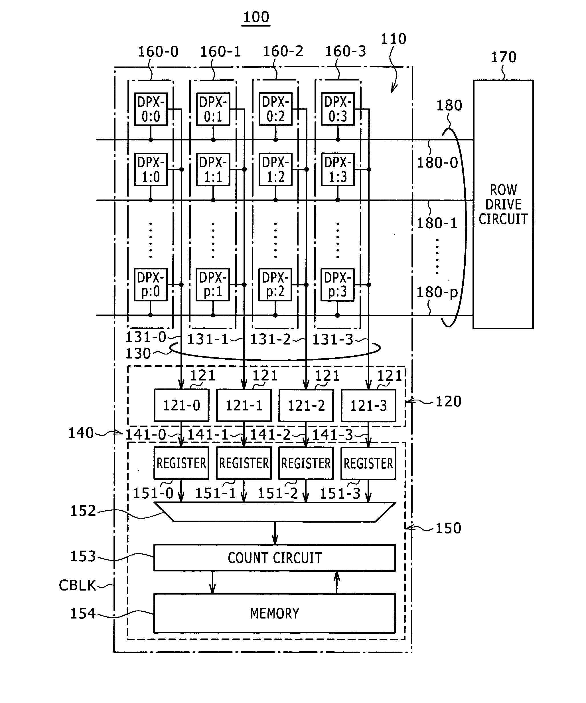
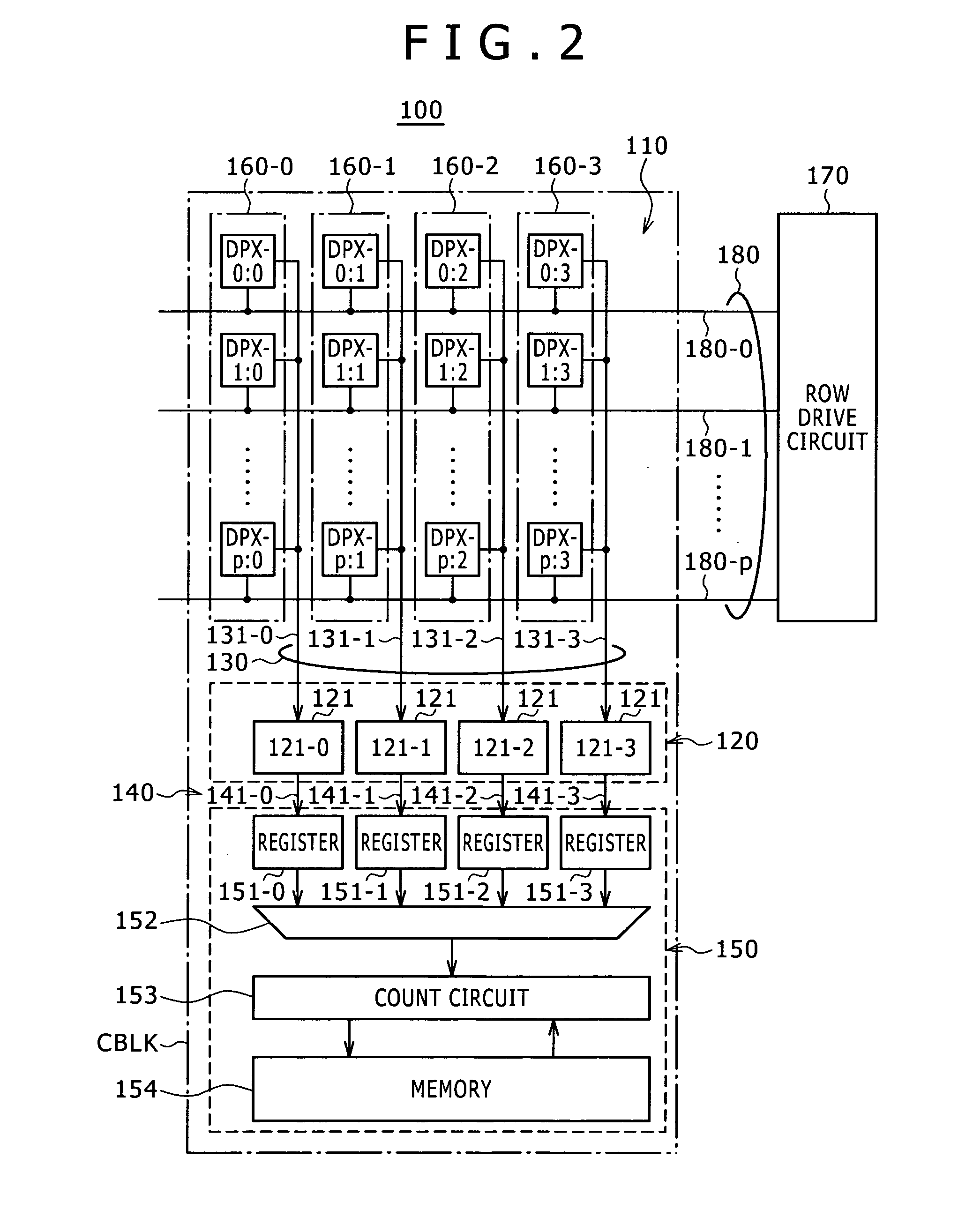
[0076]FIG. 2 is a diagram illustrating a configuration example of a CMOS image sensor (imaging element) according to a first embodiment of the present invention.
[0077][Outline of the Overall Configuration]
[0078]A present CMOS image sensor 100 includes a pixel array section 110, sensing circuit section 120, output signal line group 130, transfer line group 140 and determination result compilation circuit section 150.
[0079]In the present CMOS image sensor 100, one sensing circuit is shared among a plurality of pixels as described later.
[0080]Therefore, pixel blocks 160 are formed in the present CMOS image sensor 100, each with a plurality of pixels DPX in the same column connected by an output signal line 131 to a select circuit 121. Although pixel blocks 160-0 to 160-3 are depicted within FIG. 2, additional pixel blocks 160 can be present within the pixel array section 110.
[0081]Further, the CMOS image sensor 100 includes a row drive circuit 170 and row control lin...
second embodiment
3. Second Embodiment
[0259]FIG. 12 is a diagram illustrating an example of a pixel circuit configuration according to a present second embodiment.
[0260]A unit pixel 11C according to the present second embodiment differs from a unit pixel A according to the first embodiment in that an amplifying transistor 114B is formed with an NMOS transistor that is an n-type FET rather than a p-type FET (PMOS transistor).
[0261]The amplifying transistor 114B has its drain connected to the source potential VDD and its source connected to the output signal line 131.
[0262]In the present second embodiment, the amplifying NMOS transistor 114B has its NMOS substrate in a floating state because of its SOI (Silicon on Insulator) structure.
[0263]In a single unit pixel DPXB, photons incident upon the silicon substrate of the pixel generate electron-hole pairs. The electrons in these pairs are stored in the storage node 115 by the photodiode 111.
[0264]The electrons are transferred to the FD node 116 as the tr...
third embodiment
4. Third Embodiment
[0284]FIG. 14 is a diagram illustrating an example of a pixel circuit configuration according to a present third embodiment.
[0285]A unit pixel DPXC according to the present third embodiment differs from the unit pixel DPXA according to the first embodiment in that an amplifying transistor 114C is formed with an NMOS transistor that is an n-type FET rather than a p-type FET (PMOS transistor).
[0286]The amplifying NMOS transistor 114C has its drain connected to the source potential VDD and its source connected to the output signal line 131.
[0287]Even with the amplifying NMOS transistor 114C, the substrate thereof is electrically isolated from the substrate of other elements and connected to the output signal line 131 on the output side of the source follower.
[0288]Further, the reset NMOS transistor 113 has its drain connected to the control line 183.
[0289]The third embodiment provides the same advantageous effects as the first embodiment.
PUM
 Abstract
Description
Claims
Application Information