Cap and droplet ejecting apparatus

a technology of ejecting apparatus and droplets, which is applied in the direction of printing, other printing apparatus, etc., can solve the problems of clogging of the nozzle, difficult to control the humidity around the image forming means with the vapor generating means, and the need for new vapor generating means to be provided

Inactive Publication Date: 2007-06-28
FUJIFILM BUSINESS INNOVATION CORP
View PDF0 Cites 14 Cited by
  • Summary
  • Abstract
  • Description
  • Claims
  • Application Information

AI Technical Summary

Problems solved by technology

Water, which is used as a solvent in a water-based ink, is high in vapor pressure, and thus is evaporated with the lapse of time, which is problematic since the coloring material in the ink then solidifies.
In this case, however, the viscosity of the liquid including the curable resin may be increased by drying, whereby problems may occur in ejection.
Thus, in the ink jet system, the ejection stability of an ink jet tends to be influenced by the external environment, and nozzle clogging may occur with the passage of time.
In this method, however, vapor generating means must be newly provided, and it is hard to control the humidity around the image forming means with the vapor generating means.
In this method, however, since liquid is applied onto the recording sheet, the image quality is directly influenced, and nozzle clogging cannot be prevented unless printing is conducted frequently.
In this method, the gas to be sent must be adjusted

Method used


Image

  • Cap and droplet ejecting apparatus
  • Cap and droplet ejecting apparatus
  • Cap and droplet ejecting apparatus

Examples


first embodiment

Recording Apparatus of the First Embodiment

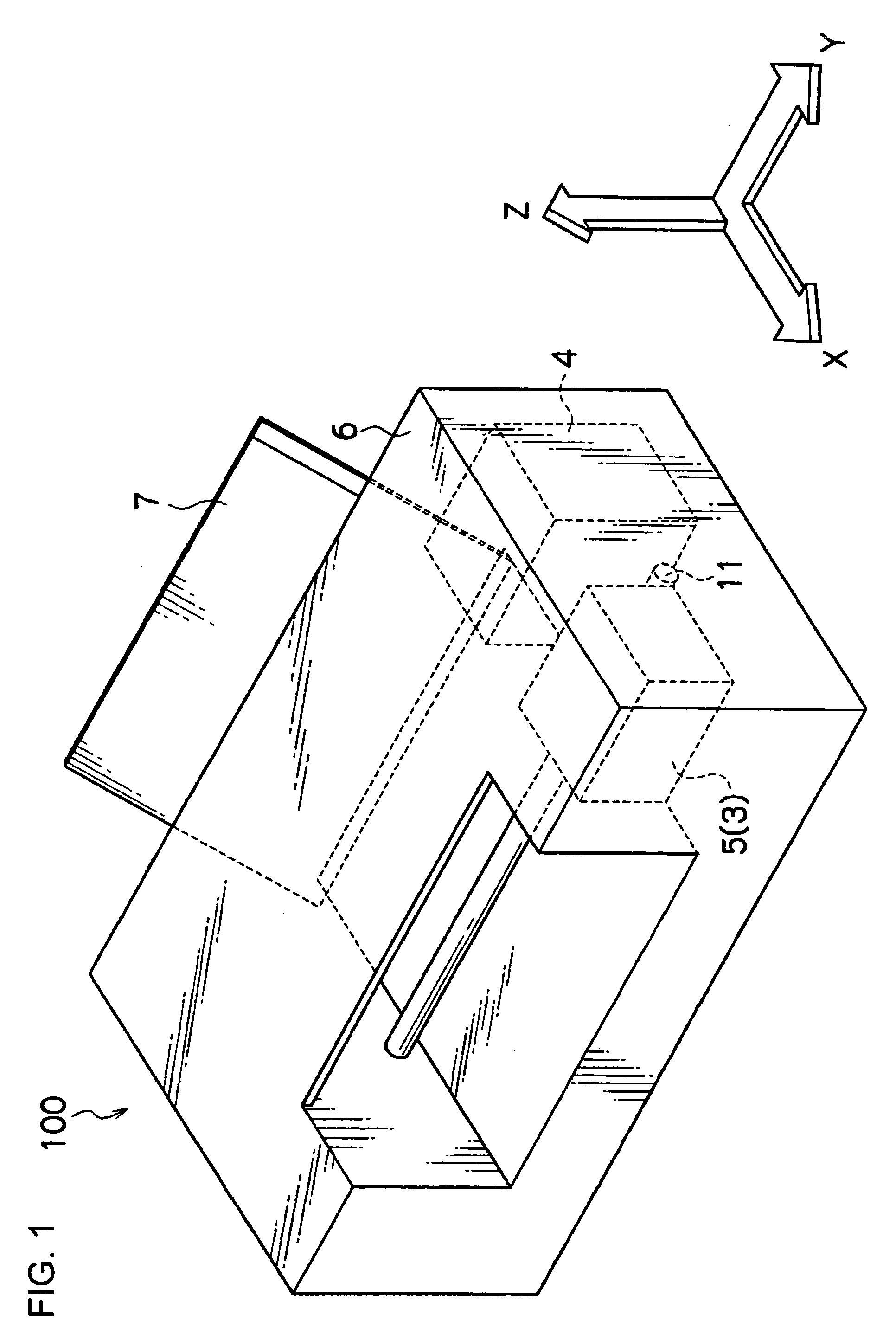
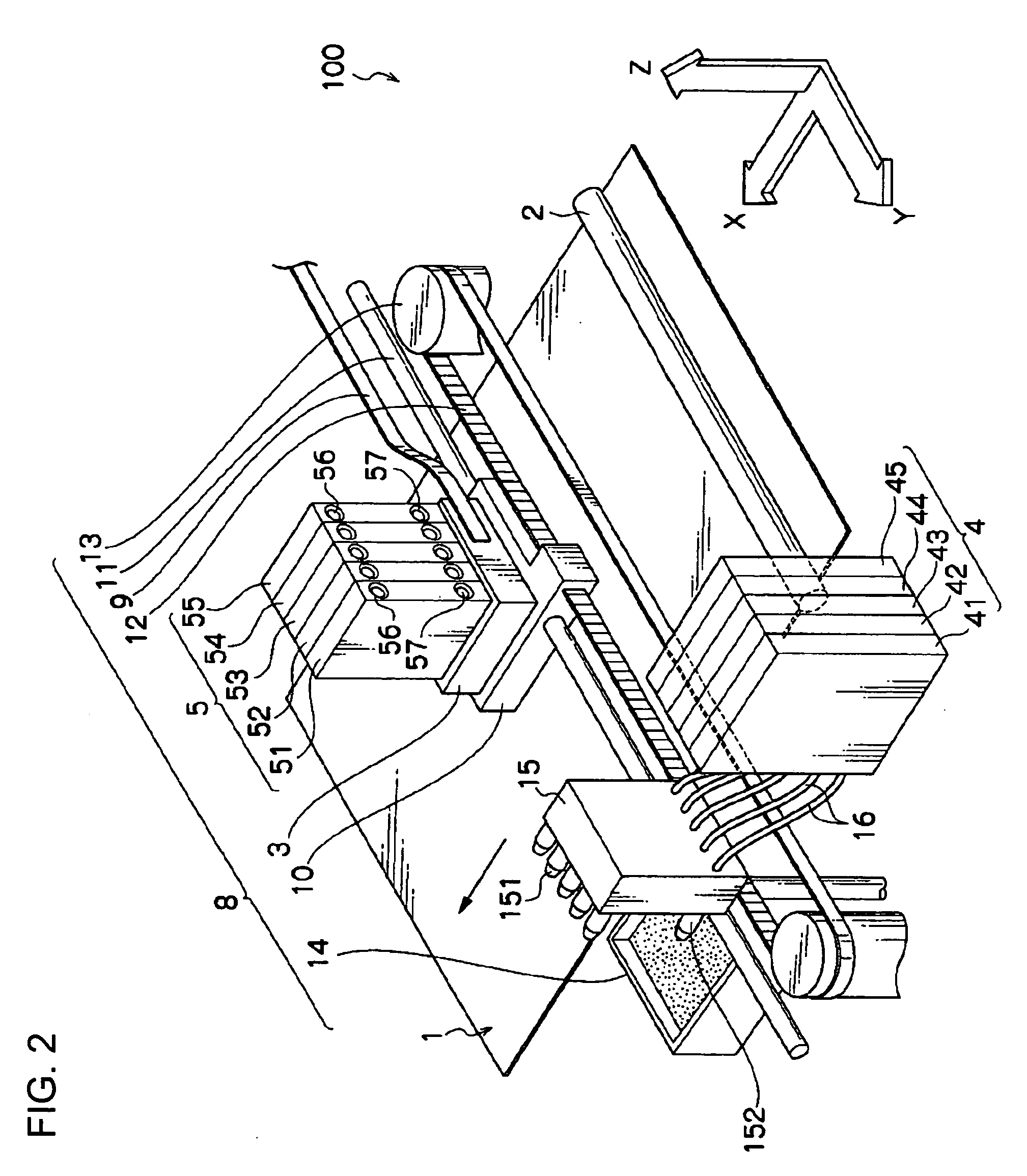
[0048]FIG. 1 is a perspective view showing an external appearance of an exemplary embodiment of an ink jet recording apparatus in the first embodiment. FIG. 2 is a perspective view showing an internal basic structure of the ink jet recording apparatus (hereinafter called “recording apparatus”) in FIG. 1. FIG. 3A and FIG. 3B are schematic views showing a structure at the nozzle surface side of the recording head 3 in this embodiment.

[0049]Referring first to FIG. 1 and FIG. 2, the configuration of the recording apparatus and its ejecting operation are described.

[0050]The recording apparatus 100 of the embodiment mainly includes, as shown in FIG. 1 and FIG. 2, an outer cover 6, a tray 7 for stacking up a specified number of sheets of a recording medium 1 such as plain paper, a conveying roller (conveying device) 2 for conveying the recording medium 1 one by one into the recording apparatus 100, an image forming unit 8 (image forming device) fo...

second embodiment

Recording Apparatus of the Second Embodiment

[0120]In the ink jet recording apparatus of the second embodiment, as a humidity regulator, a housing 21 having the humidity regulating material in its inner wall is disposed to accommodate at least the droplet ejecting head, so that the humidity around the droplet ejecting head is regulated. As a result, the humidity near the nozzles 17 provided on the droplet ejecting surface (nozzle surface) of the droplet ejecting head can be regulated. At this time, the housing 21 may be disposed so as to include the nozzles 17 (ejector) of the droplet ejecting surface internally thereof, which is favorable for regulating the humidity near the nozzles 17.

[0121]FIG. 6A and FIG. 6B are enlarged perspective views of the surroundings of the recording head 3 in this embodiment. In this embodiment, the sub ink tank 5 and recording head 3 are covered with the housing 21. As long as the housing 21 has the humidity regulating material in at least its inner wal...

third embodiment

Recording Apparatus of the Third Embodiment

[0124]In the ink jet recording apparatus of the third embodiment, as a humidity regulator, a casing having the humidity regulating material in its inner wall is disposed so as to accommodate the entire apparatus, and the humidity in the apparatus, in particular, the humidity near the nozzles 17 (ejector), is regulated.

[0125]In the third embodiment, as shown in FIG. 7, the entire ink jet recording apparatus is covered with the casing 22. The casing 22 has the humidity regulating material 18 in at least its inner wall. The entire inner wall may be covered with the humidity regulating material 18, or the humidity regulating material 18 may be adhered to the inner wall at intervals. Further, the casing 22 may be formed of the humidity regulating material 18. By covering the entire apparatus with the casing 22 having the humidity regulating material 18 in the inner wall, the humidity in the apparatus can be regulated, and thereby the humidity ne...


PUM


Abstract

The present invention provides a droplet ejecting apparatus including an ejector that ejects a liquid, and a humidity regulator that includes a humidity regulating material and regulates humidity around the ejector. The invention also provides a cap for maintaining a droplet ejecting port in an airtight condition, the droplet ejecting port being for ejecting a droplet by an ink jet system, the cap including, at least in an inner wall, a humidity regulating material containing an inorganic porous material.

Description

CROSS-REFERENCE TO RELATED APPLICATION[0001]This application claims priority under 35 USC 119 from Japanese Patent Application Nos. 2005-375917 and 2005-376229, the disclosures of which are incorporated by reference herein.BACKGROUND[0002]1. Technical Field[0003]The present invention relates to a droplet ejecting apparatus, and particularly to a droplet ejecting apparatus suppressing occurrence of nozzle clogging. The invention also relates to a cap to be provided at a liquid ejection port in an ink jet system and a droplet ejecting apparatus having the cap, and particularly to a cap and a droplet ejecting apparatus suppressing occurrence of clogging of a liquid ejection port due to drying.[0004]2. Related Art[0005]Ink jet systems for ejecting liquid from nozzles comprising nozzles, slits and porous film are used widely in various printers because of their small size and low price. Among ink jet systems, a piezo ink jet system for ejecting ink by making use of deformation of piezoel...

Claims


Application Information

Patent Timeline
IPC IPC(8): B41J29/393
CPCB41J2/1433B41J2/16508B41J2/175B41J2/17509B41J2/195
Inventor HIRAOKA, EISUKE
Owner FUJIFILM BUSINESS INNOVATION CORP
Why Eureka
Try Eureka