Multiple-beam scanning device and image forming apparatus having the multiple-beam scanning device

a scanning device and scanning device technology, applied in the direction of digitally marking record carriers, visual presentation using printers, instruments, etc., can solve the problems of increased cost, increased and uneven concentration or color change, etc., to achieve the effect of improving printing speed and time required for this process

Inactive Publication Date: 2007-06-28
RICOH KK
View PDF5 Cites 47 Cited by
  • Summary
  • Abstract
  • Description
  • Claims
  • Application Information

AI Technical Summary

Benefits of technology

[0013]Accordingly, embodiments of the present invention may provide a novel and useful multiple-beam scanning device and image forming apparatus having the multiple-beam scanning device solving one or more of the problems discussed above.
[0014]More specifically, the embodiments of the present invention may provide a multiple-beam scanning device and an image forming apparatus having the multiple-beam scanning device, in which multiple-beam scanning device i) an overlapping area over plural lines is provided in a scanning area of an optional surface of a light deflection part such as a polygon scanner and a scanning area of a neighboring surface, and thereby it is difficult to distinguish a pixel of a joint part; and ii) it is possible to implement high quality image forming without density unevenness or color change by making the joint part difficult to be distinguished in advance even if there is an unexpected reason such as vibration of the light deflection part.
[0015]The embodiments of the present invention may also provide a tandem type image forming apparatus configured to overlap toner images formed on plural image carrier body surfaces so as to form a color image whereby there is no need to individually control corresponding to each of the image carrier body surfaces and the light deflection part and the light source can be commonly used so that productivity can be improved.
[0018]According to the embodiments of the present invention, it is possible to provide a multiple-beam scanning device and an image forming apparatus having the multiple-beam scanning device, in which multiple-beam scanning device i) an overlapping area over plural lines is provided in a scanning area of an optional surface of a light deflection part such as a polygon scanner and a scanning area of a neighboring surface, and thereby it is difficult to distinguish a pixel of a joint part; and ii) it is possible to implement high quality image forming without density unevenness or color change by making the joint part difficult to be distinguished in advance even if there is an unexpected reason such as vibration of the light deflection part.
[0019]According to the embodiments of the present invention, it is also possible to provide a tandem type image forming apparatus configured to overlap toner images formed on plural image carrier body surfaces so as to form a color image whereby there is no need to individually control corresponding to each of the image carrier body surfaces and the light deflection part and the light source can be commonly used so that productivity can be improved.

Problems solved by technology

Alternatively, the sizes of pixels become uneven so that concentration unevenness or color change may occur.
However, memory capacity or a processing circuit for determining the pixel of the joint part is necessary so that cost may be raised.
In addition, since a large amount of data is processed, time required for this process cannot be ignored from the perspective of improvement of the printing speed.
Furthermore, there is no solution to change of a pitch between an end line of scanning on an optional surface generated by an unexpected reason such as vibration of the polygon scanner and a head line of scanning on a neighboring surface.

Method used


Image

  • Multiple-beam scanning device and image forming apparatus having the multiple-beam scanning device
  • Multiple-beam scanning device and image forming apparatus having the multiple-beam scanning device
  • Multiple-beam scanning device and image forming apparatus having the multiple-beam scanning device

Examples


Embodiment Construction

[0037]A description is given below, with reference to the FIG. 1 through FIG. 16 of embodiments of the present invention.

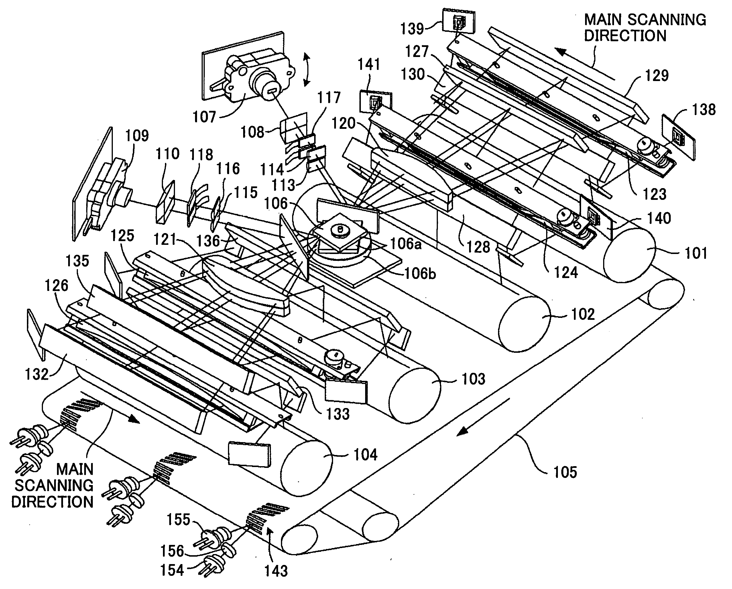
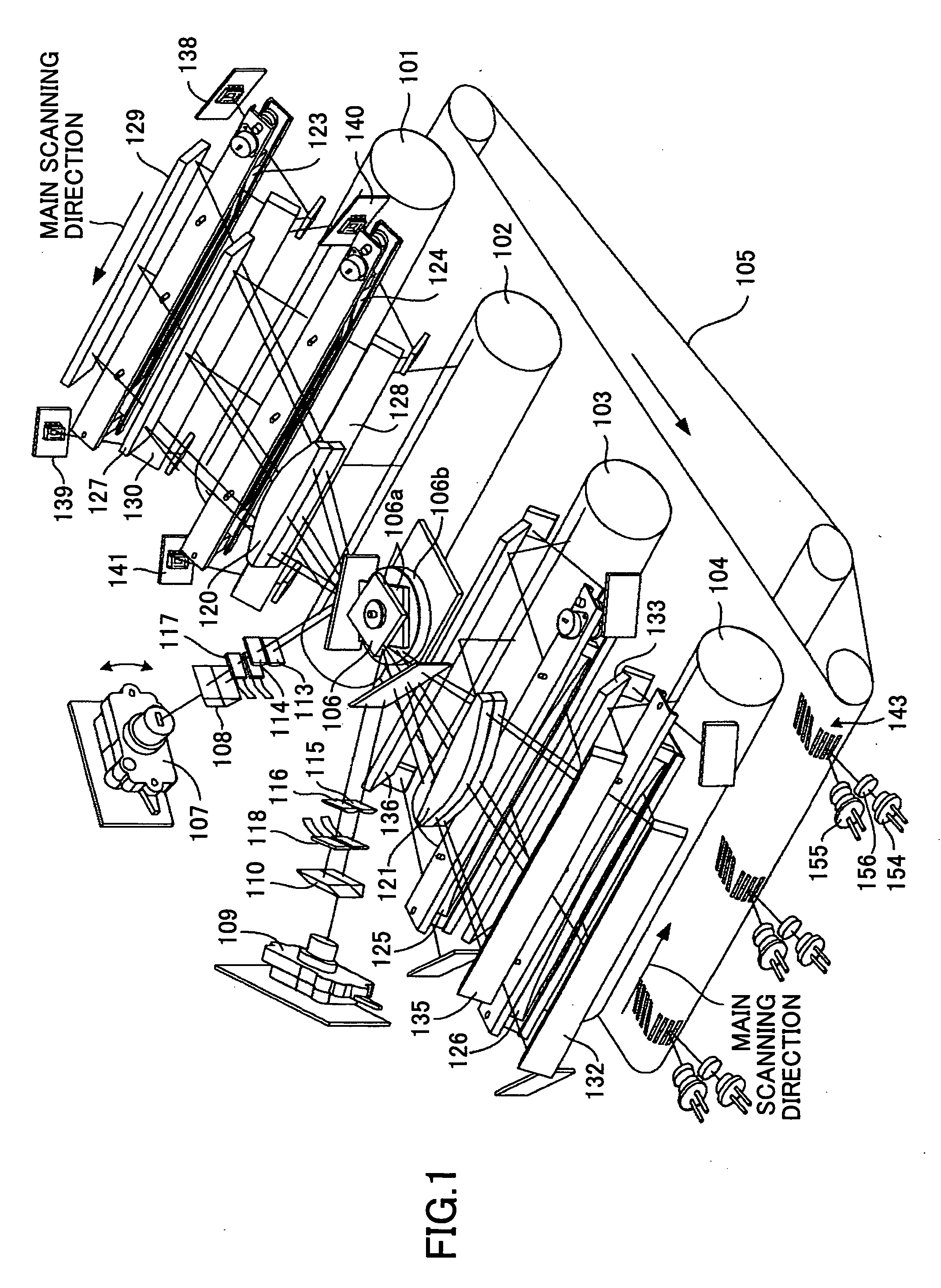
[0038]FIG. 1 is a schematic structural view of an optical scanning device (a multiple-beam scanning device) configured to scan image carrier bodies (photoconductive photosensitive drums, for example) of four image forming parts (image forming stations) of an embodiment of the present invention. More specifically, FIG. 1 shows an example of a structure of a unified optical scanning unit wherein plural light beams, corresponding to four stations, from a light source unit are scanned by a polygon mirror (polygonal rotating mirror) of a single polygon scanner so that the photosensitive drums of the four stations are scanned.

[0039]Photosensitive drums 101, 102, 103, and 104 of four image forming stations are arranged at even intervals along a moving direction indicated by an arrow of a transcription part 105 (for example, an intermediate transcription belt or a transcr...


PUM


Abstract

A multi-beam scanning device includes a light source part having a plurality of light emitting sources which light emitting sources are monolithically arranged in a surface perpendicular to an optical axis; a light deflection part configured to deflect a plurality of light beams from the light source part in a lump and scan an image carrier surface; and an image-formation optical system where lateral magnification is set so that beam spots of the plural light beams are arranged at a designated pitch in a sub-scanning direction on the image carrier surface.

Description

BACKGROUND OF THE INVENTION[0001]1. Field of the Invention[0002]The present invention generally relates to multiple-beam scanning devices and image forming apparatuses having the multiple-beam scanning devices. More specifically, the present invention relates to a scanning device used for a writing system of an image forming apparatus such as a digital copier, a laser plotter, a facsimile, or a multiple functional product thereof. Especially, the present invention relates to a multiple-beam scanning device whereby plural optical beams are simultaneously scanned so that an image is written on an image carrier body surface at a high speed, and the image forming apparatus having the multiple-beam scanning device.[0003]2. Description of the Related Art[0004]In tandem type multiple-color image forming apparatus as disclosed in, for example, Japanese Laid-Open Patent Application No. 2002-341273, image carrier bodies such as photosensitive drums corresponding to each of colors such as yell...

Claims


Application Information

Patent Timeline
Patent Type & Authority Applications(United States)
IPC IPC(8): G06K15/22
CPCB41J2/473G02B26/123G03G15/011G03G15/043G03G2215/0404G03G2215/0407G03G15/0435H04N1/1135H04N2201/04772H04N2201/04781H04N2201/04789H04N2201/04798H04N1/053
Inventor NAKAJIMA, TOMOHIRO
Owner RICOH KK
Why Eureka
Try Eureka