Eureka AIR delivers breakthrough ideas for toughest innovation challenges, trusted by R&D personnel around the world.

Vertical multi-auger mixer with blades

A mixer and vertical technology, applied in the field of vertical multi-auger mixers, can solve the problems affecting the nutritional supplement of dairy cows, waste of feed, etc.

Pending Publication Date: 2017-12-26
SHANDONG AGRICULTURAL UNIVERSITY
View PDF0 Cites 3 Cited by
  • Summary
  • Abstract
  • Description
  • Claims
  • Application Information

AI Technical Summary

Problems solved by technology

If the roughage is not reduced to the size of millet grains, the cows will leave large pieces of roughage in the trough and only eat rice grain silage and protein supplements, resulting in waste of feed and affecting the nutritional supplementation of cows

Method used


Image

  • Vertical multi-auger mixer with blades
  • Vertical multi-auger mixer with blades
  • Vertical multi-auger mixer with blades

Examples


Embodiment 1

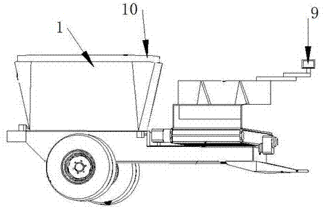
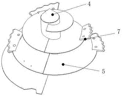
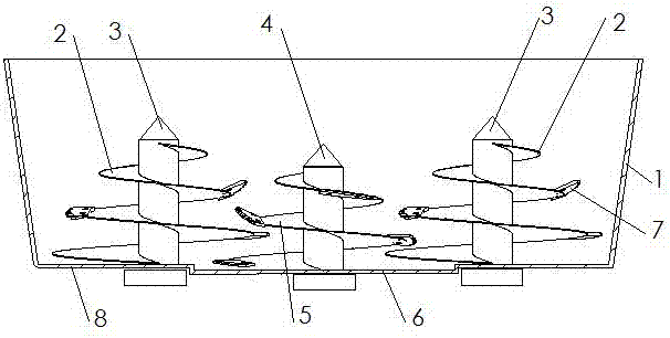
[0019] Such as image 3 A vertical multi-auger mixer with blades is shown, comprising a material box with a bottom wall and a continuous side wall 1, a frame supporting the material box, and a weight measuring device installed between the frame and the material box.

[0020] The bottom wall includes a main bottom wall 6 and two secondary bottom walls 8 located on both sides of the main bottom wall 6 and higher than the main bottom wall 6 , the main bottom wall 6 and the secondary bottom walls 8 are arranged horizontally. The main bottom wall 6 is equipped with a vertical main transmission shaft 4 through a bearing, and the vertical main transmission shaft 4 is driven to rotate by the driving device, and the vertical secondary transmission shaft 3 is installed on the secondary bottom wall 8 through a bearing. The power transmission shaft 3 is also connected with a driving device that drives its rotation. The driving device in this embodiment can be an electric motor or other ty...

Embodiment 2

[0028] The difference between this embodiment and Embodiment 1 is that the main bottom wall in this embodiment is located at one end of the bottom wall, and the two secondary bottom walls are located at one side of the main bottom wall, and the heights are increased successively, so that the forage grass that is crushed can be drawn from one end. Gradually transfer to the other end to prevent the main screw blade from bringing the feed to the secondary bottom wall during discharge, improving the discharge efficiency.

[0029] During use, the vertical main transmission shaft 4 and the vertical secondary transmission shaft 3 can be selected to rotate in opposite directions to improve the cutting efficiency of forage grass. The feed lifted by the helical blades moves outward from the upper part of the main transmission shaft and the vertical secondary transmission shaft to the side wall of the feed box, and then moves downwards towards the bottom wall. When the feed reaches the b...


PUM


Abstract

The invention relates to a vertical multi-auger mixer with blades, which comprises a bin with a bottom wall and a continuous sidewall, the bottom wall comprises a primary bottom wall and at least one secondary bottom wall higher than the main bottom wall, a vertical primary drive shaft and vertical secondary drive shafts which are driven by a driving device to rotate are respectively mounted on the primary bottom wall and the secondary bottom wall, a primary spiral blade and secondary spiral blades are respectively fixed on the vertical primary drive shaft and the vertical secondary drive shafts, a plurality of blades are mounted on the outer edge of each of the primary spiral blade and the secondary spiral blades, and at least one blade on the primary spiral blade and the blades on the secondary spiral blades are formed into the shape of scissors; and a discharge door which is opposite to the vertical primary drive shaft is arranged on the continuous sidewall. By means of the primary spiral blade and the secondary spiral blades, the vertical multi-auger mixer repetitively cuts a large bundle of forage into finely cut blocks, so that the forage and other feeds cannot be easily distinguished by milk cows after being mixed, and thereby the situation that milk cows only eat granular feeds, such as silage and protein supplement, is prevented.

Description

technical field [0001] The invention relates to the technical field of mixers, in particular to a mixer for chopping and mixing dairy cow feed, in particular to a vertical multi-auger mixer with blades. Background technique [0002] Food sources for feeding dairy cows include roughage, silage, and protein supplements, among others. Roughage includes pastures and other vegetation such as clover, alfalfa, etc. Silage is a variety of green plants that are chopped into small pieces and fermented in silos, and protein supplements are usually ground or stacked pellets. Commonly used grains include corn, fishmeal, soybeans, barley, and oats, and alfalfa can be processed and used as a protein supplement. In most cases, harvested forage is dried and baled. Bales are usually large round or large square bales. Large round and rectangular bales typically weigh between 550kg and 900kg and the forage can also be dried and stored. Roughage can be mixed with silage or protein supplemen...

Claims


Application Information

Patent Timeline
IPC IPC(8): B01F7/24A23N17/00
CPCA23N17/00A23N17/007B01F27/172B01F27/191B01F27/2322B01F27/84B01F27/922B01F27/85
Inventor 田富洋陈玉华李法德闫银发宋占华李玉道王春森陈为峰
Owner SHANDONG AGRICULTURAL UNIVERSITY
Why Eureka
Eureka Blog
Learn More