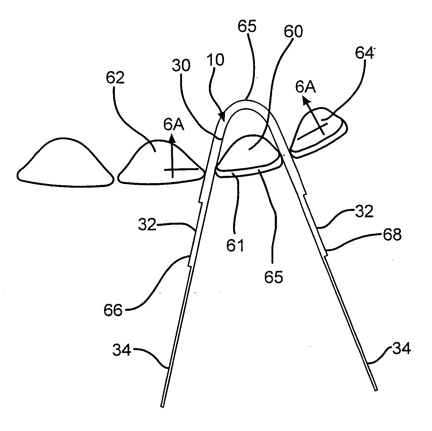
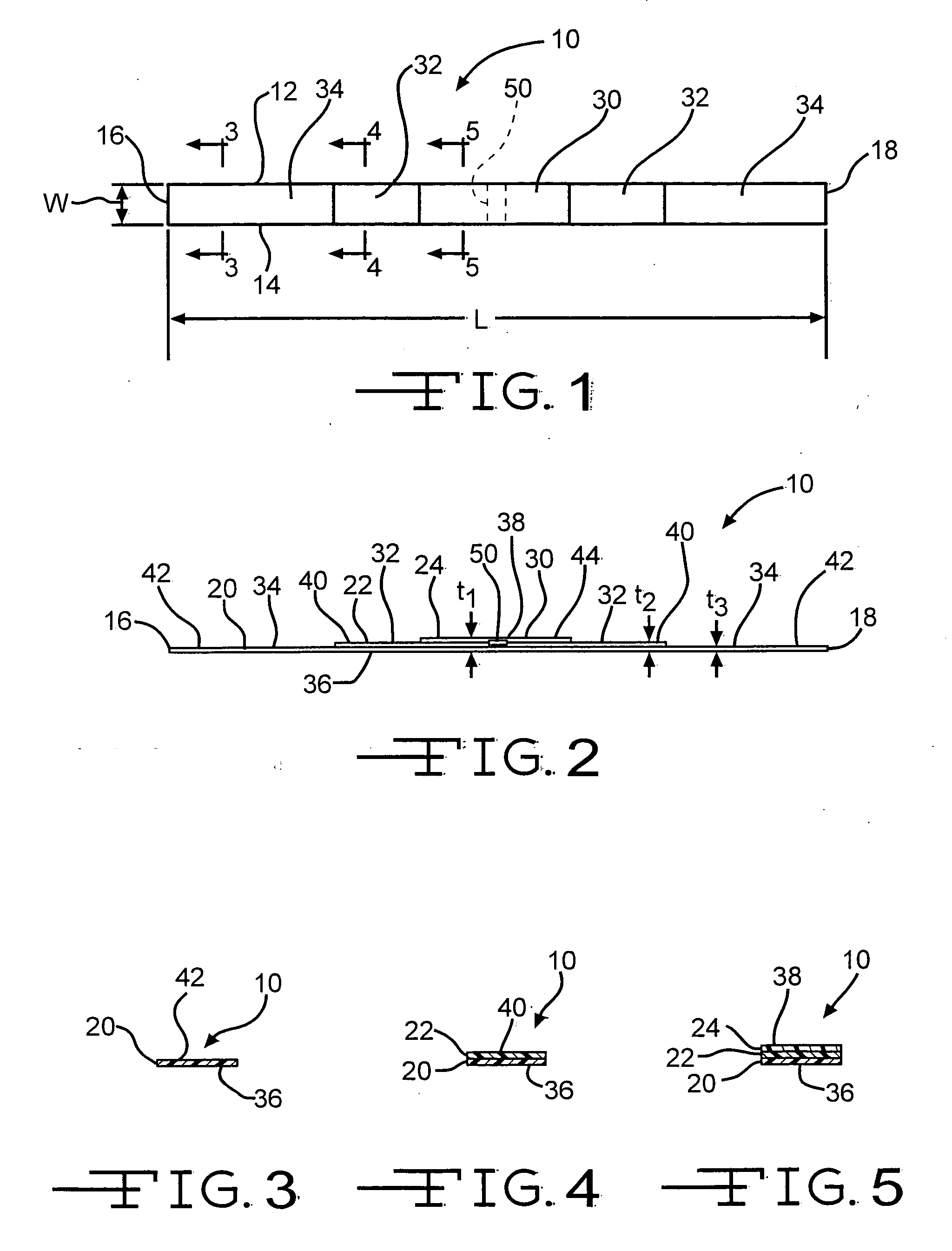
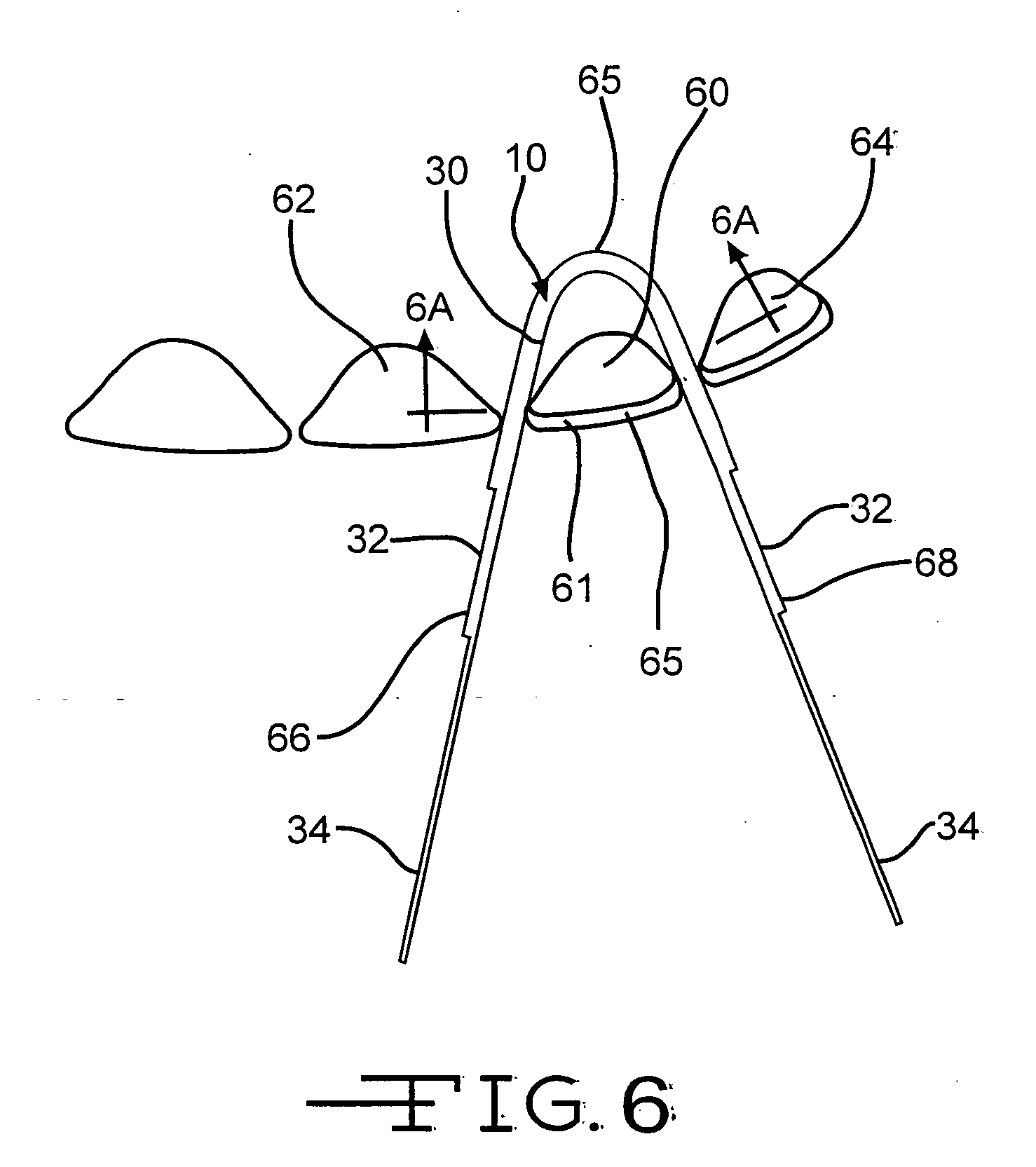
Dental strip
- Summary
- Abstract
- Description
- Claims
- Application Information
AI Technical Summary
Problems solved by technology
Method used
Image
Examples
second embodiment
[0049]There is illustrated in FIGS. 7 through 11 a dental strip, indicated generally at 100, which may also be used in dental procedures for isolating or shielding the sides of adjacent teeth. The strip 100 defines a lateral width W2 between edges 112 and 114. The strip 100 further defines a longitudinal length L2 between ends 116 and 118. Preferably, the width W2 of the strip 100 remains constant along the length of the strip 100, as best shown in FIG. 7. However, it should be understood that the width W2 need not remain constant along the length.
[0050]The strip 100 is preferably made of a flexible material, such as plastic, such that it is easily manipulated within and exterior of a patient's mouth. The strip 100 may also be transparent to assist the dentist in viewing through the strip 100 during dental procedures and to facilitate light curing through the strip 100. Preferably, the strip 100 includes indicia 150 locating the approximate center of the length of the strip 100. Alt...
third embodiment
[0058]There is illustrated in FIG. 12 a dental strip, indicated generally at 200. The strip 200 includes a generally flat planar rear surface 202 and a front surface 204. The strip also includes ends 206 and 208. The strip has a generally thin central portion 210 and thicker end portions 212. The front surface 204 tapers upwardly from the central portion 210 towards both ends 206 and 208.
[0059]The strip 200 can be used to isolate adjacent teeth such that the strip 200 is generally folded in half at the central portion 210 which is then inserted between adjacent teeth. The strip 200 is then pulled at the fold such that the thickness of the strip 200 between the teeth increases as the strip 200 is pulled through between the teeth.
fourth embodiment
[0060]There is illustrated in FIG. 13 a dental strip, indicated generally at 220. The strip 220 is similar in function and structure as the strip 200 of FIG. 12 with an exception that the strip 220 has a rear surface 222 which is also tapered along with a tapered front surface 224. The taper on a first half portion 226 may be differently shaped from the taper on a second half portion 228, thereby creating different thickness of the strip 220 along the length of the first and second half portions 226 and 228 even though spaced equidistant from the center of the strip 220.
[0061]In an alternate embodiment of a strip (not shown), the strip may be tapered from one end continuously to the other end increasing in thickness such that the strip has a contour similar to the first or second half portions 226 and 228 of the strip 220. If desired, the strip 220 may be cut in half prior to use, thereby providing two single tapered strips. Alternatively, an alternate embodiment of a strip (not sho...
PUM
 Abstract
Description
Claims
Application Information
 - R&D
- Intellectual Property
- Life Sciences
- Materials
- Tech Scout
- Unparalleled Data Quality
- Higher Quality Content
- 60% Fewer Hallucinations
Browse by: Latest US Patents, China's latest patents, Technical Efficacy Thesaurus, Application Domain, Technology Topic, Popular Technical Reports.
© 2025 PatSnap. All rights reserved.Legal|Privacy policy|Modern Slavery Act Transparency Statement|Sitemap|About US| Contact US: help@patsnap.com


