

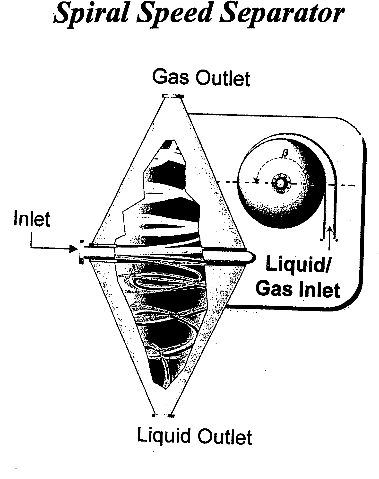
Spiral Speed Separator (SSS)
a spiral separator and separator technology, applied in the direction of separation process, liquid degasification, filtration separation, etc., can solve the problems of low separation efficiency and still a lot of carryover due to
- Summary
- Abstract
- Description
- Claims
- Application Information
AI Technical Summary
Benefits of technology
Problems solved by technology
Method used
Image

Examples
Embodiment Construction
[0007] The invention relates to a unique method efficiently separation of various streams or fluids such as: [0008] Gases or Vapors from Liquids [0009] Gases or Vapors from Solids [0010] Liquids from Solids
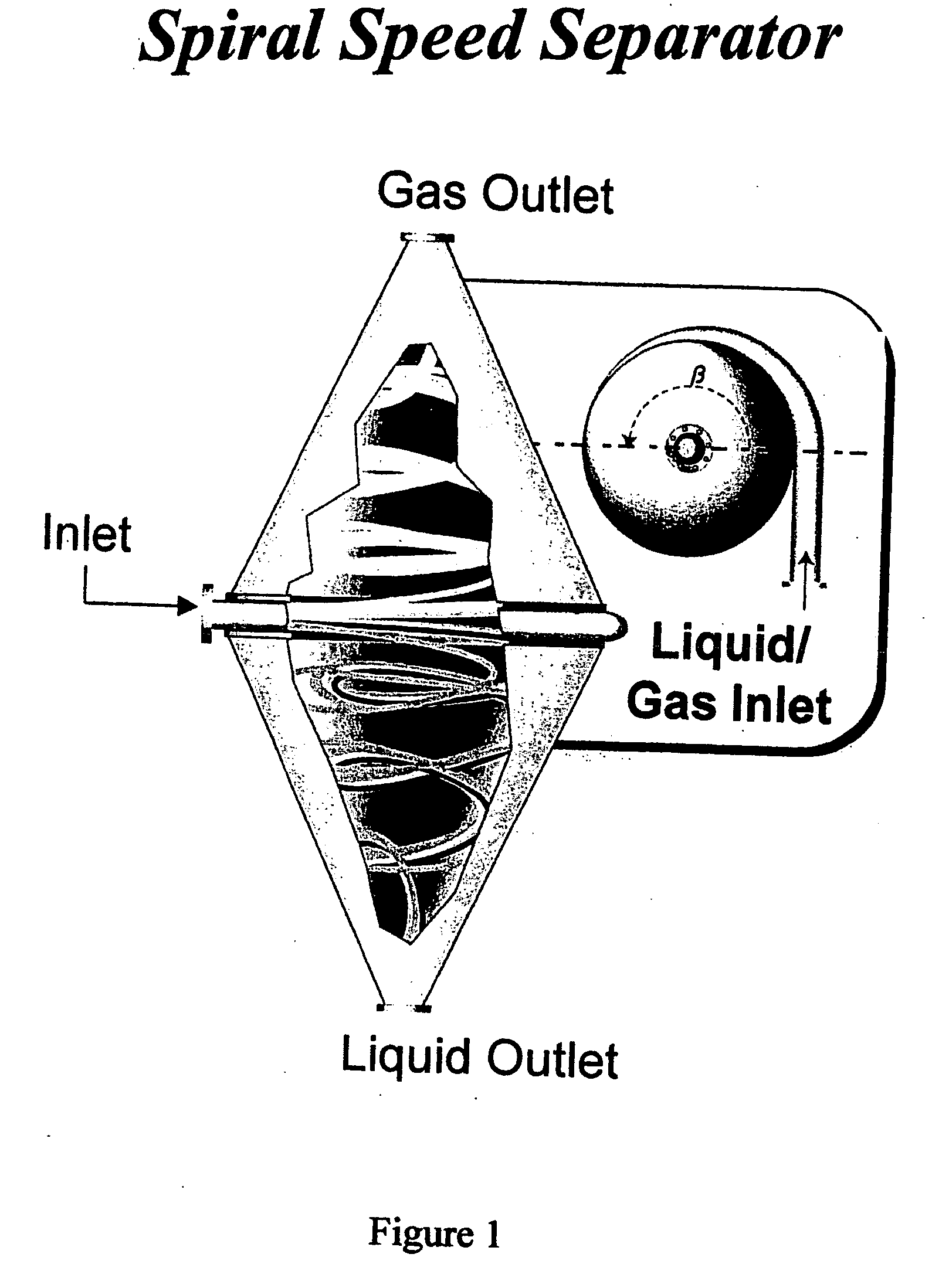
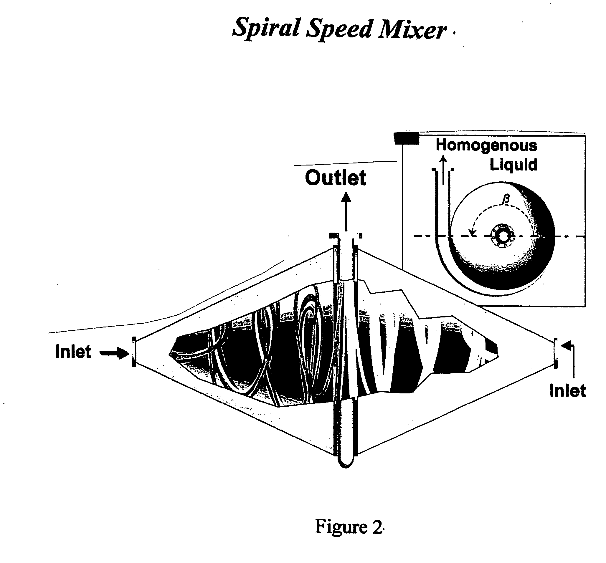
[0011] The combination and creation of the fluid's centrifugal and gravitational forces through a tangential projection with the directional vanes in both zones with equal distance and volume is the basis for the Spiral Speed Separator. The angle of the tangential flow is shown by the angle β in the FIG. 1. The fluids' kinetic energy is used to create all the effects which result in efficient separation than the conventional systems. This phenomenon will result in a far superior separation among the different fluids and also highly efficient for mixing and blending different fluids.
PUM
| Property | Measurement | Unit |
|---|---|---|
| volume | aaaaa | aaaaa |
Abstract
Description
Claims
Application Information