Throttle position sensor

Active Publication Date: 2007-07-12
HARLEY DAVIDSON MOTOR COMPANY GROUP INC +1
View PDF55 Cites 20 Cited by
  • Summary
  • Abstract
  • Description
  • Claims
  • Application Information

AI Technical Summary

Problems solved by technology

However, in circumstances where the interior passageway is obstructed, such as when a throttle position sensor for an electronic throt

Method used


Image

  • Throttle position sensor
  • Throttle position sensor
  • Throttle position sensor

Examples


Embodiment Construction

.

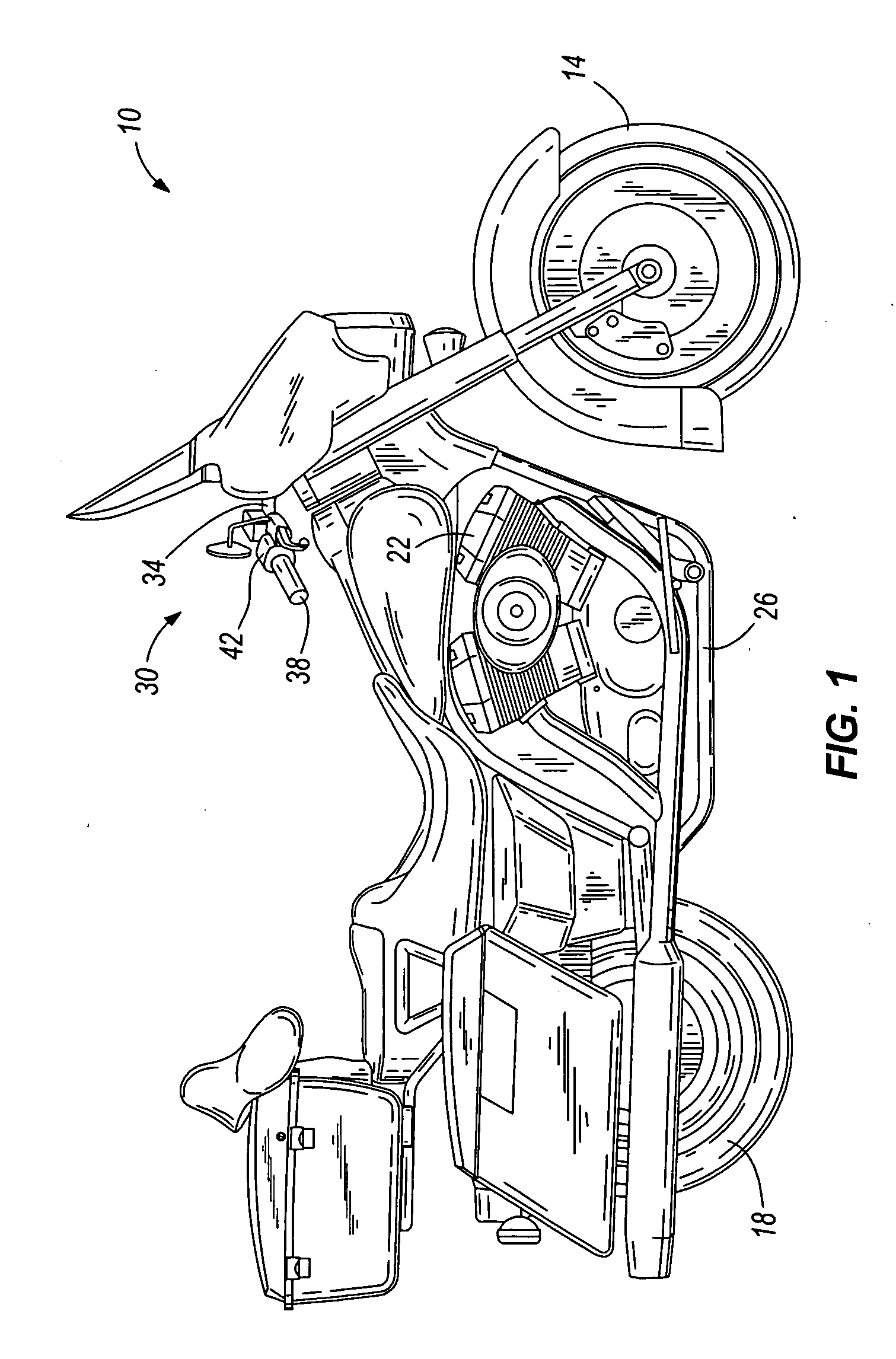
[0021]FIG. 1 illustrates a motorcycle 10 including a front wheel 14, a rear wheel 18, an engine 22, and a frame 26 interconnecting the front and rear wheels 14, 18. The motorcycle 10 also includes a steering assembly 30 coupled to the frame 26. The steering assembly 30 is pivotable about a steering axis and includes a handlebar 34 for imparting such pivotal motion to the steering assembly 30. The handlebar 34 includes a left-side grip (not shown) and a right-side grip 38 that are grasped by an operator to control the motorcycle 10.

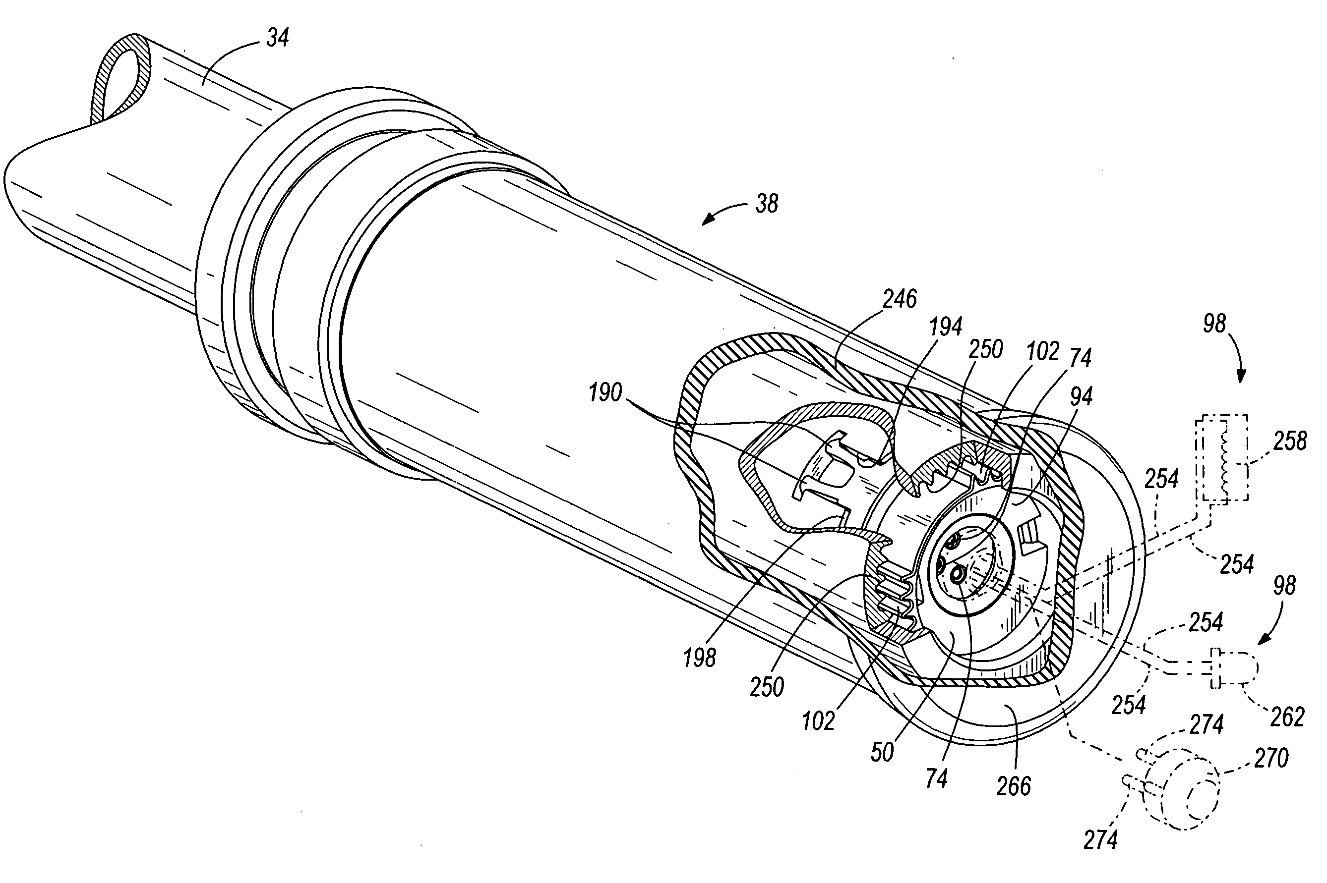
[0022] The left-side grip is secured to the left-hand end portion of the handlebar 34, and the right-side grip or throttle grip 38 is secured to the right-hand end portion of the handlebar 34. A left control housing (not shown) is positioned inwardly of the left-side grip, and a right control housing 42 is positioned inwardly of the throttle grip 38. The left control housing and right control housing 42 are secured to the motorcycle handlebar 34. The lef...


PUM


Abstract

The present invention provides a throttle position sensor for a motorcycle including a handlebar having an end. The throttle position sensor includes a rotor having a first end and a second end. The rotor is positioned within the handlebar and rotated relative to the handlebar. The second end is closer than the first end to the end of the handlebar. The throttle position sensor also includes a sensor operable to detect rotation of the rotor relative to the handlebar and generate a signal corresponding to the rotation of the rotor relative to the handlebar. The throttle position sensor further includes at least one electrical conduit passing into the rotor from the first end. The at least one electrical conduit is routed through the rotor and is accessible from the second end of the rotor.

Description

FIELD OF THE INVENTION [0001] This invention relates generally to motorcycles, and more particularly to throttle position sensors for motorcycles. BACKGROUND OF THE INVENTION [0002] Motorcycle owners often purchase various accessories for their motorcycles. Among other accessories, a motorcycle owner may purchase handlebar lights and heated throttle grips for their motorcycle. Such handlebar lights are commonly installed at the ends of the respective handlebars, and the heated throttle grips are installed in place of the original throttle grips. [0003] To provide electrical power to the handlebar lights or heated throttle grips, electrical wires or cords can be routed through the interior passageway of the hollow, tubular handlebars to electrically connect to a source of power, such as the motorcycle's battery. However, in circumstances where the interior passageway is obstructed, such as when a throttle position sensor for an electronic throttle is located inside the interior passa...

Claims


Application Information

Patent Timeline
IPC IPC(8): F02D11/04G05G1/08B62K21/12B62J99/00
CPCB62K23/04Y10T74/2078Y10T74/20486G01D5/145
Inventor POSSEHL, KELLYPALFENIER, SAMLEHMEN, ALLENRICHLEN, JEFFCROWE, WILLIAM E.
Owner HARLEY DAVIDSON MOTOR COMPANY GROUP INC
Why Eureka
Try Eureka