
Stuffing box assembly and sealing assembly for use therein

Inactive Publication Date: 2007-08-02
UTEX IND
View PDF25 Cites 14 Cited by
  • Summary
  • Abstract
  • Description
  • Claims
  • Application Information

AI Technical Summary

Problems solved by technology

Depending on the depth of the well and / or well conditions, drilling fluid pressures can reach several thousand psi, and at these high pressures, conventional, prior art packing assemblies used to seal between the wash pipe and the rotary head to which the drill pipe is secured have reduced life, resulting in leaking.
In particular, as deeper wells are drilled at higher mud pressures, e.g., 6,000 psi, turning rates of 220 rpm and high flow rates of drilling mud, the wearing problem on the seals between the wash pipe and the rotary head to which the drill pipe is secured is exacerbated.
As is well known to those skilled in the art, once the packing fails, it is necessary to stop the drilling and replace the packing, an operation that in and of itself can take eight to ten hours.
Furthermore, this is not the total downtime before drilling can be resumed.
It is becoming increasingly apparent that these typical prior art packings made from the materials described above do not have sufficient lifetime when operating under severe conditions of high mud pressures, high turning rates and high flow rates.
Thus, while more sophisticated materials such as PTFE, PTFE alloys, high temperature plastics and rigid elastomers / rubber composites can withstand these harsh operating conditions, they have disadvantages which affect their sealing ability.
These materials, while they perform well initially, lose their sealing ability once the drilling is stopped and / or the mud pressure is reduced, e.g., when it is necessary to add a new joint of drill string or for some other reason encountered in the drilling operation.
Typically these materials are generally hard or rigid elastomers, plastics, etc., and generally yield under the initial stress and accordingly, lose their interference engagement with the wash pipe, such that when mud pressure is brought back up to operating conditions leakage occurs.
As noted above, conventional packing materials of softer elastomers / rubber composites have sufficient elasticity to maintain a sealing force under high or low PV's, but they have poor wear characteristics.

Method used


Image

  • Stuffing box assembly and sealing assembly for use therein
  • Stuffing box assembly and sealing assembly for use therein
  • Stuffing box assembly and sealing assembly for use therein

Examples


Embodiment Construction

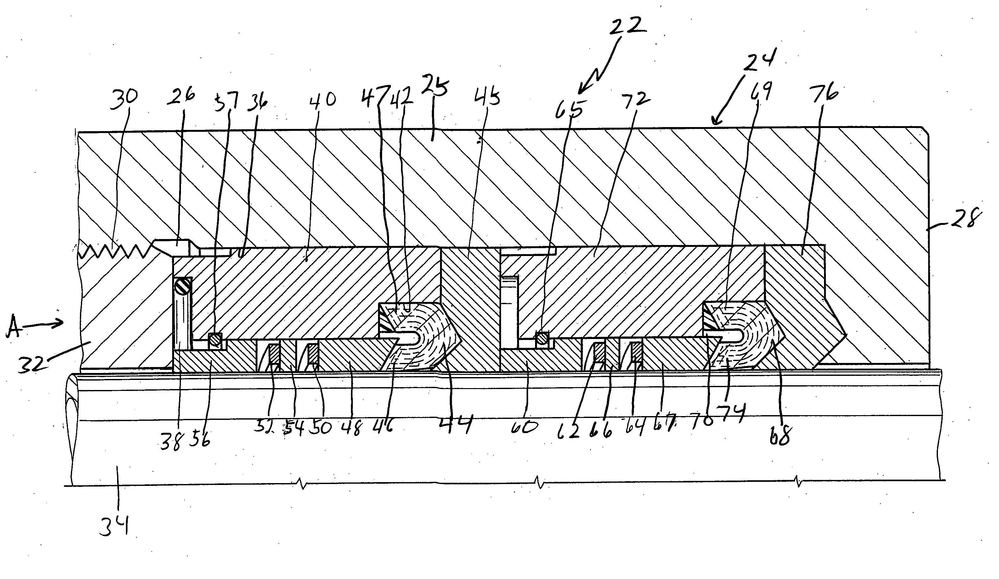
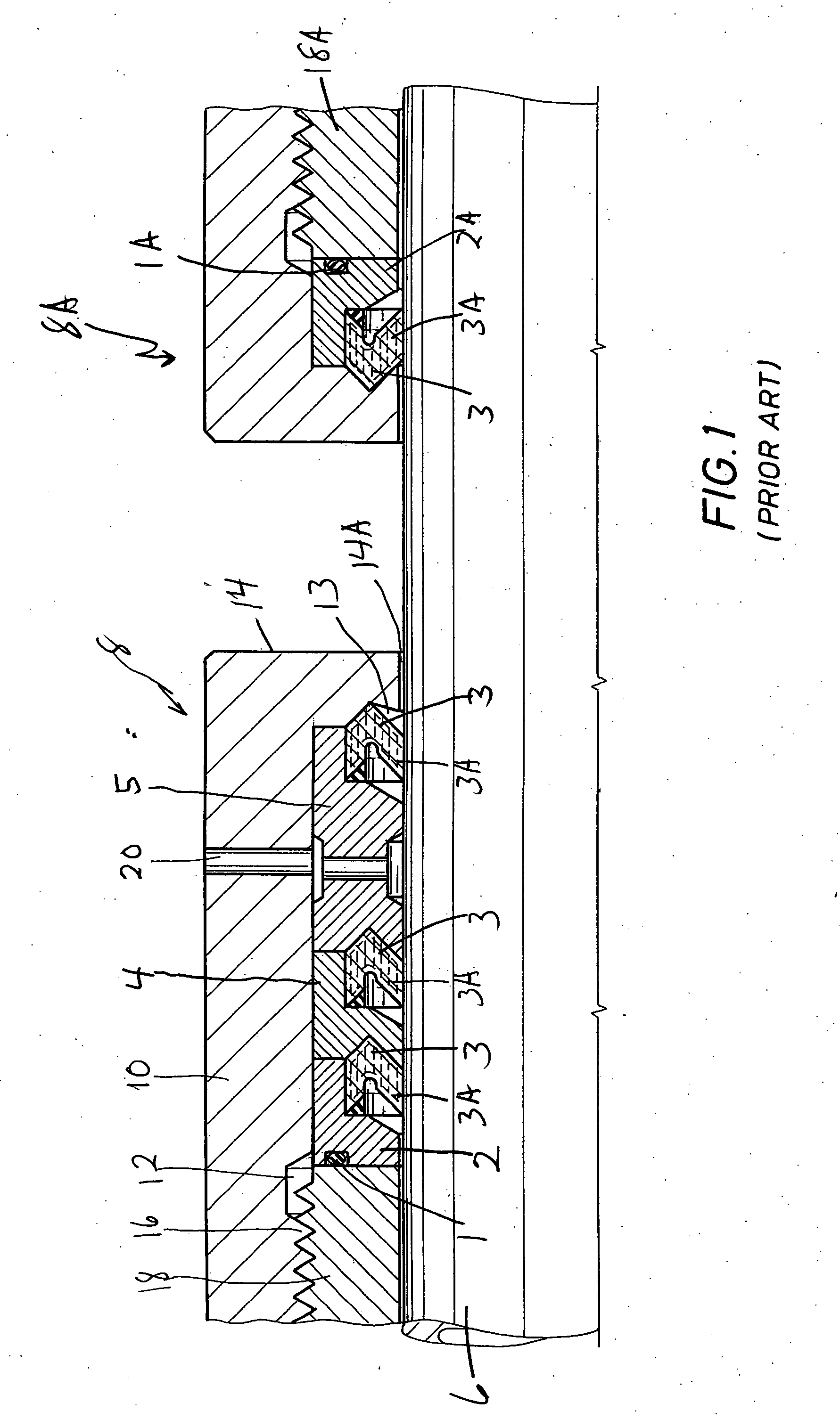
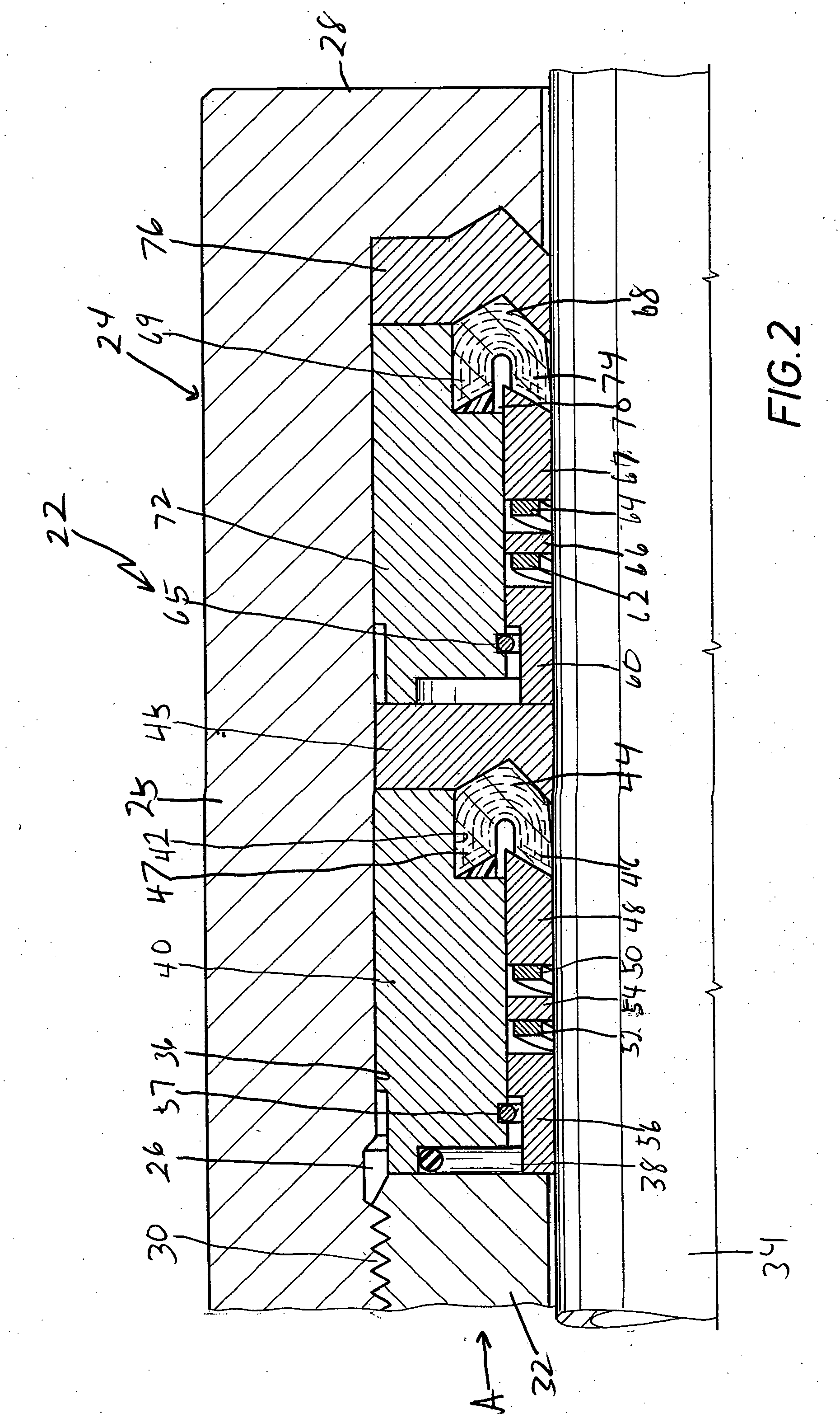
[0017] Referring first to FIG. 1, there is shown a wash pipe / stuffing box or packing gland assembly used in a conventional rotary drilling swivel, the stuffing box assembly including a conventional prior art sealing or packing assembly, all of which are well known to those skilled in the art. Referring then to FIG. 1, a wash pipe 6 extends through a stuffing box assembly shown generally as 8 comprising a packing gland or stuffing box housing 10 forming an annular chamber 12 in surrounding relationship to wash pipe 6. Housing 10 has a first end wall 14 having a bore 14A therethrough and a second end (partially shown) which is threaded as at 16 to receive a threaded follower 18. As seen, there is a second stuffing box assembly 8A which is substantially a mirror image of assembly 8. Positioned in the annulus in chamber 12 surrounding wash pipe 6 is an annular seal ring carrier 2 which is sealed against follower 18 by means of an O-ring 1. An annular lip type seal ring 3 carried by carr...


PUM


Abstract

A stuffing box assembly for use in sealing between a fixed housing and a rotatable member extending through the fixed housing comprising a housing forming a sealing assembly chamber, a rotatable member extending through the housing and a sealing assembly received in the chamber, the sealing assembly including an annular seal ring carrier, an annular seal ring carried by the carrier, the seal ring having an annular radially outer portion and an annular radially inwardly extending sealing lip, an annular seal ring spreader operatively engaged with the seal ring, an elastic biasing member operatively engaged with the seal ring spreader and an annular adjustable follower selectively axially immovable with respect to the housing, the spreader exerting a greater force on the sealing lip than the radially outer portion of the seal lip when the spreader is biased towards the seal ring.

Description

CROSS-REFERENCE OF RELATED APPLICATION [0001] This Application Claims Priority from Provisional Application No. 60 / 736,891 filed Oct. 15, 2005 for Packing Assembly For Rotary Drilling Swivels, the disclosure of which is incorporated herein by reference for all purposes BACKGROUND OF THE INVENTION [0002] 1. Field of the Invention [0003] The present invention relates to a stuffing box and a sealing assembly for use in effecting fluid sealing between a fixed body and a rotating body and, in particular around the wash pipe of a rotary drilling swivel. [0004] 2. Description of Prior Art [0005] In the drilling of oil and gas wells, a drill bit is rotated in a borehole by means of a string of drill pipe. The drill pipe is rotated on the surface mechanically by a rotating table mounted on a drilling platform or by a hydraulic motor, commonly referred to as a top drive. As is common in such oil and gas well drilling, drilling fluid or mud is circulated through the drill pipe and the drill bi...

Claims


Application Information

Patent Timeline
IPC IPC(8): E21B19/00
CPCF16K41/083E21B33/08
Inventor PIPPERT, FREDERICK B.
Owner UTEX IND
Learn More