Cartridge for machine tool

a technology for machine tools and cartridges, which is applied in the direction of shaping tools, forging/hammering/pressing machines, forging presses, etc., can solve the problems of cartridge wear and tear, cartridge breakage, and heavy weight of cast iron cartridges

Active Publication Date: 2007-08-16
WILSON TOOL INT
View PDF32 Cites 27 Cited by
  • Summary
  • Abstract
  • Description
  • Claims
  • Application Information

AI Technical Summary

Problems solved by technology

Since cartridges are moved by the machine tool, there is often wear and tear on the cartridges.
This can result in cartridge breakage.
However, these cast iron cartridges are very heavy.
As a result, they are less than ideal in terms of their great inertia, which adversely impacts the dynamic performance of a machine tool in loading, unload

Method used


Image

  • Cartridge for machine tool
  • Cartridge for machine tool
  • Cartridge for machine tool

Examples


Embodiment Construction

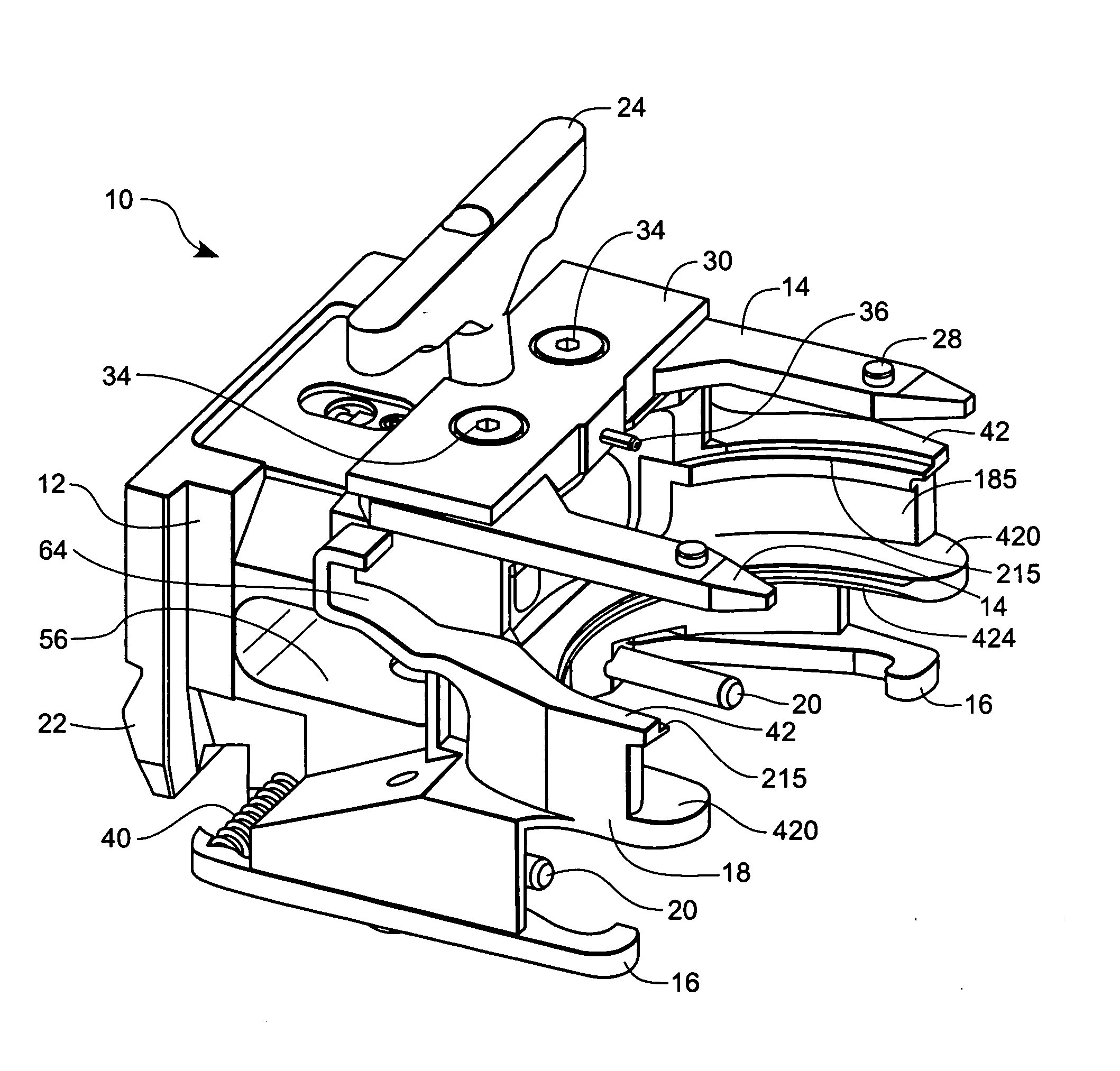
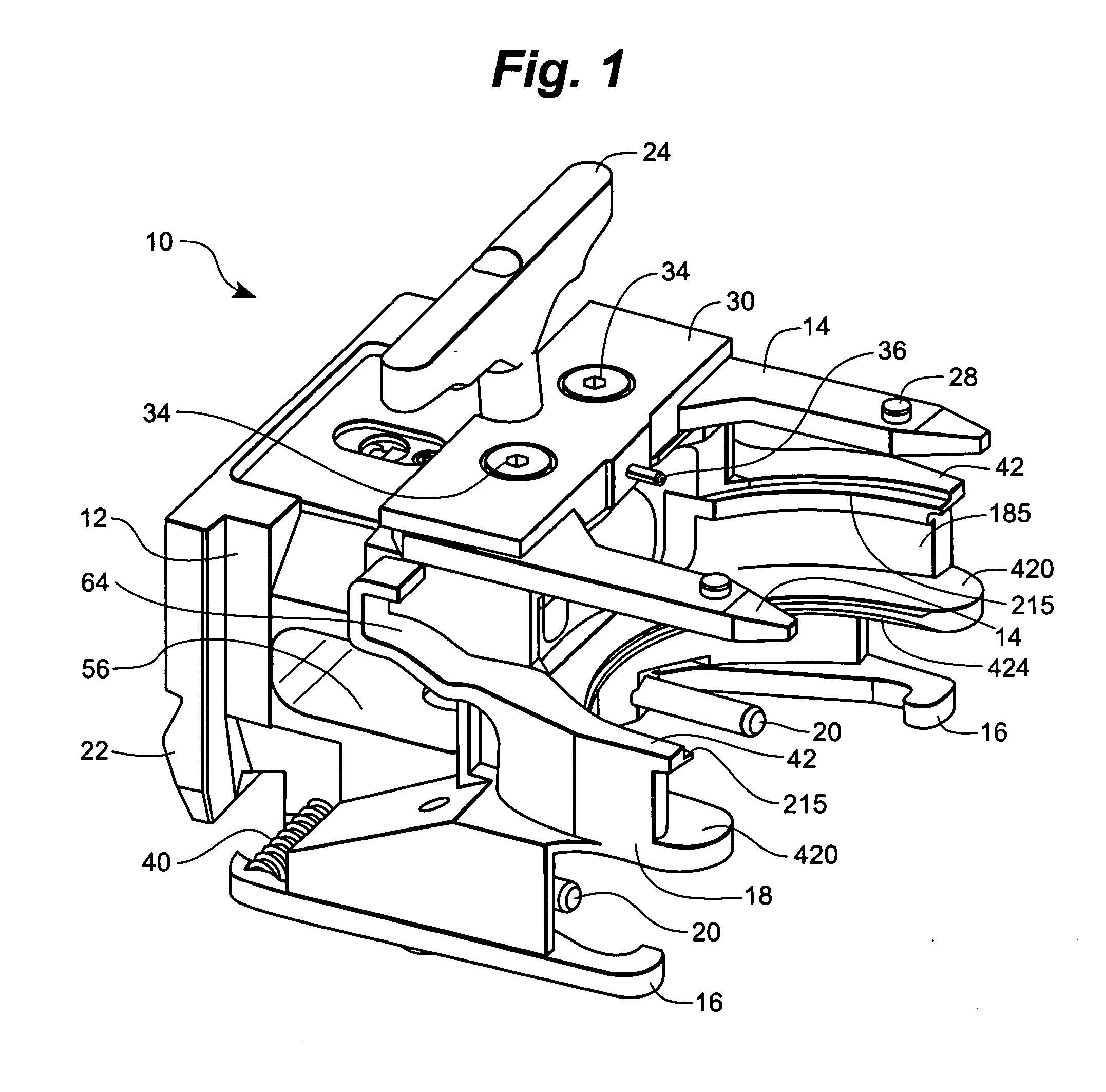
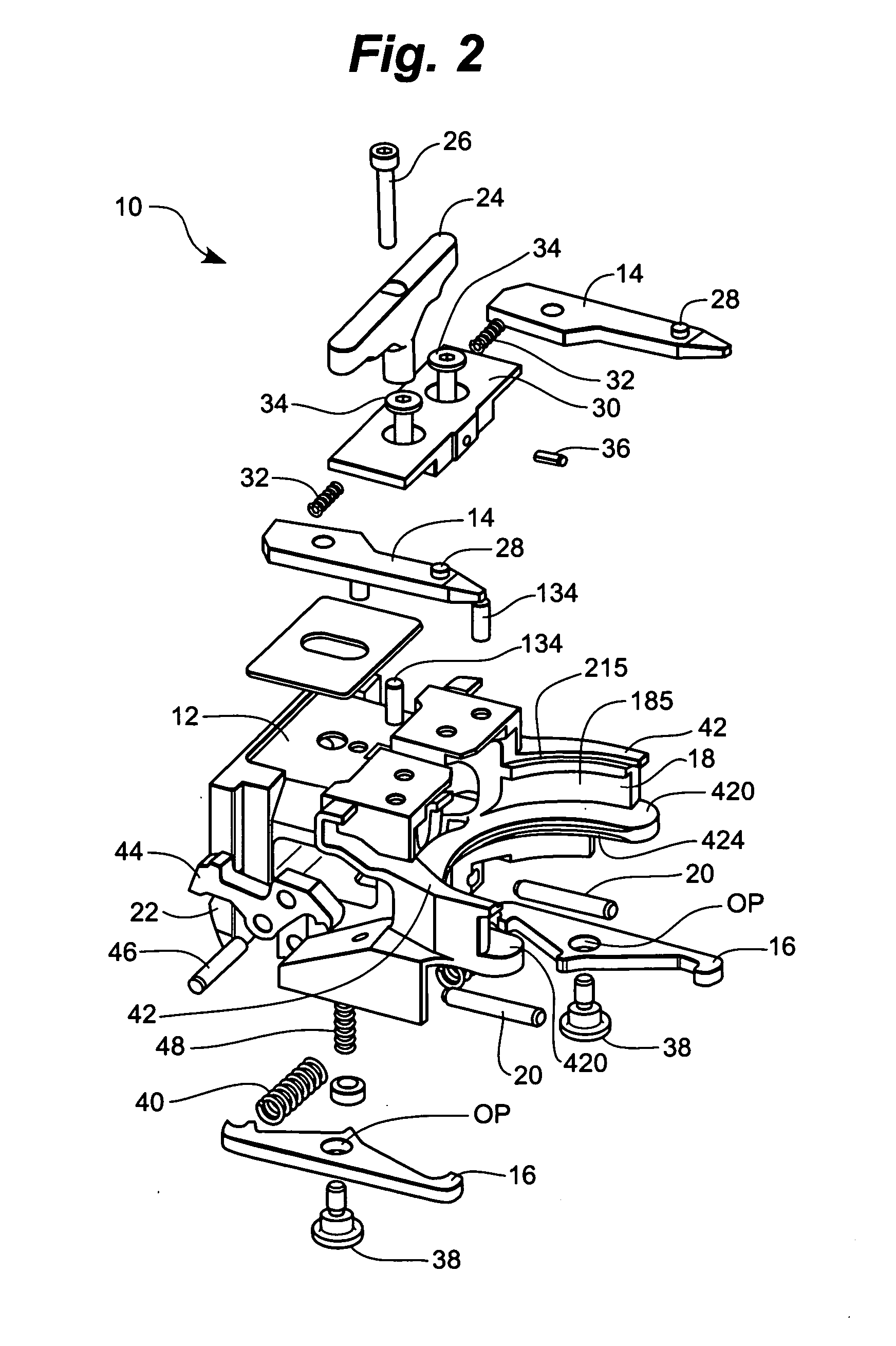
[0037] With reference to the figures, a tool cartridge 10 is provided having a main body 12, two punch-retention arms 14, and two die-retention arms 16. The illustrated cartridge has (optionally its main body has) an upper portion 12a, a middle portion 12b, and a lower portion 12c. The punch-retention arms 14 preferably extend outwardly from the upper portion 12a, and the die-retention arms 16 preferably extend outwardly from the lower portion 12c. In the figures, the two punch-retention arms 14 are spaced apart from each other and are generally parallel to each other. Likewise, the illustrated die-retention arms 16 are spaced apart from each other and are generally parallel to each other. In other embodiments, though, the arms 14 are not generally parallel and / or the arms 16 are not generally parallel. The illustrated punch-retention arms 14 are generally parallel to the die-retention arms 16, although this may not be the case in all embodiments.

[0038] The main body 12 preferably ...


PUM

PropertyMeasurementUnit
Weightaaaaaaaaaa
Weightaaaaaaaaaa
Massaaaaaaaaaa

Abstract

A cartridge for a machine tool is provided. The cartridge has a main body, two punch-retention arms, and two die-retention arms. Preferably, the two punch-retention arms are spaced apart and at least generally parallel to each other. Likewise, the two die-retention arms preferably are spaced apart and at least generally parallel to each other. In some cases, the main body is formed of a first metal, and the punch-retention arms and die-retention arms are formed of metal(s) different than the first metal. In one group of embodiments, the invention provides a cartridge having a weight of less than 3 pounds.

Description

FIELD OF THE INVENTION [0001] The invention relates generally to cartridges for holding tool sets. More particularly, the invention relates to cartridges for holding tool sets for machine tools. BACKGROUND OF THE INVENTION [0002] Machine tools are usually adapted for being used with many different tool sets. A typical tool set includes a punch and a corresponding die. A stripper plate is also commonly included as part of the tool set. In processing a workpiece (e.g., a piece of sheet metal), it is common to use several different tool sets. In some cases, once a first tool set has been used, it is exchanged for a second tool set, and then a third, and so on. Once a first workpiece has been fully processed using the desired sequence of tool sets, a second workpiece may be processed, in some cases beginning again with the first tool set. [0003] The tool sets used on a machine tool commonly are stored in cartridges. Some cartridges may be stored in the machine tool, while others may be ...

Claims


Application Information

Patent Timeline
IPC IPC(8): B23Q3/155
CPCY10T483/1729B23Q3/15553B21D28/34B21D37/147
Inventor PALICK, RONALDLEE, BRIAN J.MOREHEAD, JOHN H.TIMP, RICHARD L.
Owner WILSON TOOL INT
Why Eureka
Try Eureka